3D of GDL is capable of far more than described in the Basic 3D elements lesson of this tutorial.
Let’s take a look at the more complex commands for using planar shapes in 3D, creating polyline-based bodies and cutting.
Planar Shapes in 3D
Most 2D commands have their 3D counterparts in GDL:
- LIN_
- RECT
- POLY_
- CIRCLE
- ARC
…and so on. For the complete list, take a look at the Planar Shapes in 3D section of the GDL manual.
These 2D shapes are placed onto the current x-y plane of the 3D space, defined by previous transformations.
Example:
Let’s create a lampion in 2 colors, rotating a planar circle polygon by 20 degrees steps.
! ------------------------------------------------------------------------------
! Input parameters controlled by the user:
! ------------------------------------------------------------------------------
! matLampion1: (Surface) parameter
! matLampion2: (Surface) parameter
! radiusPar:   (Length) parameter
! _nTans:      variable for transformation stack
! _iCircle:     iteration variable

_nTans = 0

for _iCircle = 0 to 160 step 20
	roty 20
	if _iCircle % 40 = 0 then
		material matLampion1
	else
		material matLampion2
	endif
	circle radiusPar
	_nTans = _nTans + 1
next _iCircle

del _nTans
Note: the LIN_ element is not visible in rendering.
Polyline-based bodies in 3D
Many forms can be created by using one or more polylines as base, by projecting their points following a rule, a path (another polyline) or rotation.
For the full arsenal, check out the Shapes Generated from Polylines section of the GDL manual.
These commands can be very similar to the PRISM_ commands, using the same additional status codes, but usually have a different method of projection.
Solid element operations in GDL
Sometimes it is more easy to create a body using two separately defined element than trying to define the whole in a single command (and sometimes it is not even possible).
Using solid element operation commands inside GDL, the following options are available:
- forming the Boolean union of 2 solids (by ADDGROUP function)
- the difference of such solids is available as well (by SUBGROUP fuction)
- creating the Boolean intersection of 2 solids (by ISECTGROUP command)
- only the intersection lines can be generated (by ISECTLINES command)
- and sweeping a body along a vector is also possible (by SWEEPGROUP command)
The base method is simple: define goups of bodies (base and tool) with GROUP command you want to interact with each other, then define the interaction, and place the resulting body (using PLACEGROUP command). Groups no longer needed should be cleared from the memory by using KILLGROUP command.
A group definition is somewhat special the GDL script:
- bodies defined inside it are placed, not visible unless commanded (PLACEGROUP), but merely exist in solid element operations space
- must have a unique “name” within the script, just like subroutines
- a group can not contain another group definition, can not be nested
- transformations and cuttings defined inside the group definition have no effect outside, and vice-versa
- attribute settings, on the other hand, are effective inside and outside as well
For more detailed explanation and examples, check out the Solid Geometry Commands section of the GDL manual.
Example:
group "block"
	material matBlock
	block 1, 1, 1
endgroup

group "sphere"
	material matSphere
	add 1, 1, 1
	sphere 1
	del 1
endgroup

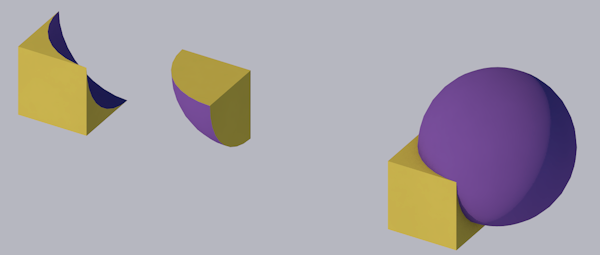
resultGroup = SUBGROUP("block", "sphere")
placegroup resultGroup
addx 2.2

resultGroup2 = ISECTGROUP("block", "sphere")
placegroup resultGroup2
addx 2.2

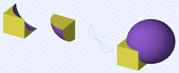
resultGroup3 = ISECTLINES("block", "sphere")
placegroup resultGroup3
addx 2.2

resultGroup4 = ADDGROUP("block", "sphere")
placegroup resultGroup4

del 3
killgroup "block"
killgroup "sphere"
Result in rendering:

Result in 3D:

Cutting in 3D
There is a special set of commands for cutting bodies in 3D:
- CUTPLANE: the cutting surface is defined by a plane
- CUTPOLY: the cutting surface is defined by a polygon
- CUTSHAPE: the cutting surface is defined by a body
- CUTFORM
