Creating a Tread element for the new Stair tool
Example object for this post can be downloaded here.
Since the new Stair and Railing tools has been introduced in ARCHICAD 21, Tread library elements can be scripted for the Stair tool in GDL. This post helps getting through the available Stair tread 2D-3D global variables under the Tread Component subtype.
Origo of the Tread
The origo of a Tread is on the intersection of the Walking Line and the top of the Tread. The edited Walking Line Symbol is not considerated into the position of the origo.
! Sizes
_coordSize	= 0.1
_shapeSize	= 0.01
_smallThk	= 0.001

! Local coordinate system
sphere _smallThk

pen 58					! X axis, red pen
lin_ 0, 0, 0, _coordSize, 0, 0
pen 4					! Y axis, green pen
lin_ 0, 0, 0, 0, _coordSize, 0
pen 46					! Z axis, blue pen
lin_ 0, 0, 0, 0, 0, _coordSize
Geometry of the Tread
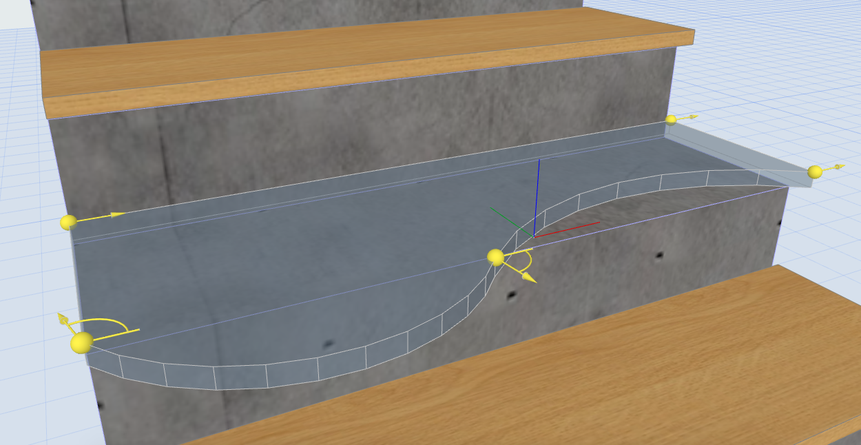
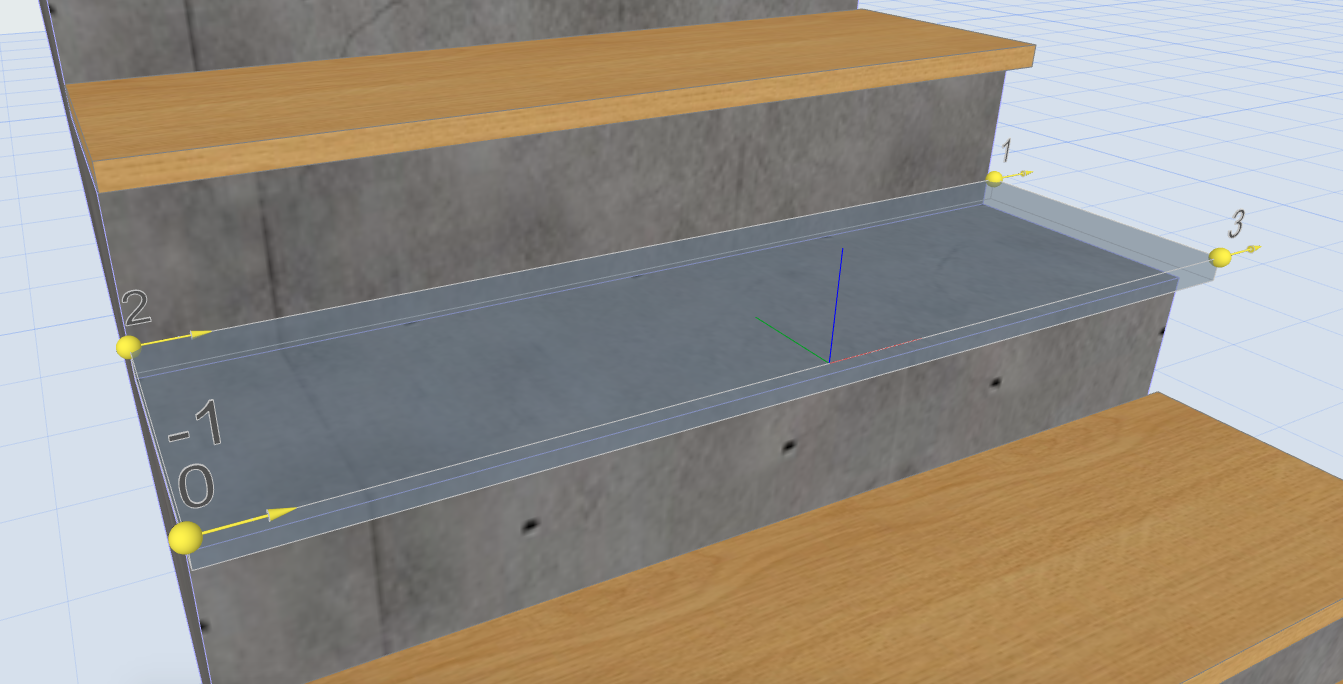
The geometry of a Tread is given in the STAIR_TREAD_GEOMETRY[][3] global variable. Each Tread can be edited separately, so this global gives the geometry of the actual Tread, relative to the position of the Tread’s origo. The nodes are given in counter-clockwise order. The last node position is the same as the first node’s, the angle which belongs to the last node is 0.
The following script shows the values of this global variable graphically in 3D. Spheres are placed to the node coordinates, the angle is shown by an arc and an arrow, measured from the direction of the Tread original local coordinate system’s X axis.
for _vert = 1 to vardim1(STAIR_TREAD_GEOMETRY)
    add STAIR_TREAD_GEOMETRY[_vert][1], STAIR_TREAD_GEOMETRY[_vert][2], 0
    sphere _shapeSize

    roty 90
    cylind _coordSize/2, _smallThk

    rotz 90
    addz _coordSize/2 - _shapeSize
    roty 90
    if STAIR_TREAD_GEOMETRY[_vert][3] < EPS then 		! clockwise arc direction
        mulz -1
    endif

    elbow _coordSize/2 - _shapeSize, abs(STAIR_TREAD_GEOMETRY[_vert][3]), _smallThk

    if STAIR_TREAD_GEOMETRY[_vert][3] < EPS then
        del 1
    endif
    del 4

    rotz STAIR_TREAD_GEOMETRY[_vert][3]
    roty 90
    cylind _coordSize/2, _smallThk

    addz _coordSize/2
    cone _shapeSize * 2, _smallThk * 4, 0, 90, 90

    del 3
    del 1
next _vert
Note that the clockwise arc directions are represented as negative values to the in the Tread's coordinate system.
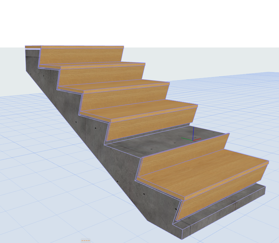
Creating a Tread prism
Based on the STAIR_TREAD_GEOMETRY[][3] global variable, we can create a prism for the Tread. The arcs are given in a signed angle value, which has to be recalculated to a form which is compatible with the Additional Status Codes. In the following scripts the arcs are given by the 900 - Set centerpoint and the 4000 - Arc using centerpoint and angle Status Codes.
From the coordinates of the two node points and the value of the angle which belongs to the first vertex point the coordinates of the centerpoint can be calculated. For this method, the BasicGeometricCalc macro is used by giving the DIRECTION_SEGMENT as the calculation method (iFunction = 3). For the usage of the BasicGeometricCalc macro see the Using BasicGeometricCalc macro post.
The BasicGeometricCalc macro returns the given arc's start and end direction vector coordinates and the arc's centerpoint coordinates. For the prism points only the centerpoint coordinates are needed, so in the following script _dummy variables are used for the vector coordinates.
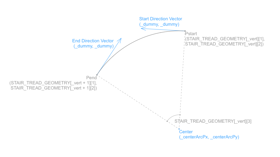
The vertex points are put in internal parameter buffer, then the PRISM_ command gets the stored polygon data. The height of the prism is given by the TREAD_THICKNESS global variable.
addz -TREAD_THICKNESS

for _vert = 1 to vardim1(STAIR_TREAD_FLAGS) - 1			! Last Vertex point has no angle
    if abs(STAIR_TREAD_GEOMETRY[_vert][3]) > EPS then		! The next edge is arched

        call "BasicGeometricCalc" parameters  iFunction	= 3,	! DIRECTION_SEGMENT
        				      startPx	= STAIR_TREAD_GEOMETRY[_vert][1],
        				      startPy	= STAIR_TREAD_GEOMETRY[_vert][2],
        				      endPx	= STAIR_TREAD_GEOMETRY[_vert + 1][1],
        				      endPy	= STAIR_TREAD_GEOMETRY[_vert + 1][2],
        				      arcAngle	= STAIR_TREAD_GEOMETRY[_vert][3],
        		returned_parameters   _dummy,
        				      _dummy,
        				      _dummy,
        				      _dummy,
        				      _centerArcPx,
        				      _centerArcPy

        ! Put the prism controlpoints using additional status codes
        put STAIR_TREAD_GEOMETRY[_vert][1],	STAIR_TREAD_GEOMETRY[_vert][2],	  15
        put _centerArcPx, 			_centerArcPy, 			  900
        put 0, 					STAIR_TREAD_GEOMETRY[_vert][3],   4000 + 15
    else
        ! Put the prism controlpoints directly from the global variable
        put STAIR_TREAD_GEOMETRY[_vert][1], STAIR_TREAD_GEOMETRY[_vert][2], 15
    endif
next _vert

prism_ 	nsp / 3, TREAD_THICKNESS,
    get(nsp)

del 1
Tread Edge Flags
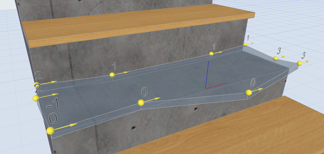
The edges of a Stair Tread can have four different status: Leading edge, Right edge, Left edge, Trailing edge. These statuses can be needed to create different behaviour on the edges - such as nosing, accessory, etc. The status of an edge is given in the STAIR_TREAD_FLAGS[ ][1] global variable, where eachedge flag status belongs to the starting node point. The order of the edge flags corresponds with the order of the nodes in the STAIR_TREAD_GEOMETRY[ ][3] global variable. To the last node no edge belongs, the value of the edge flag is -1.
In the example object edge flag values can be written above each starting node. Simple Tread:
Edited Tread with more edges on each side:
Upper and Lower Riser globals
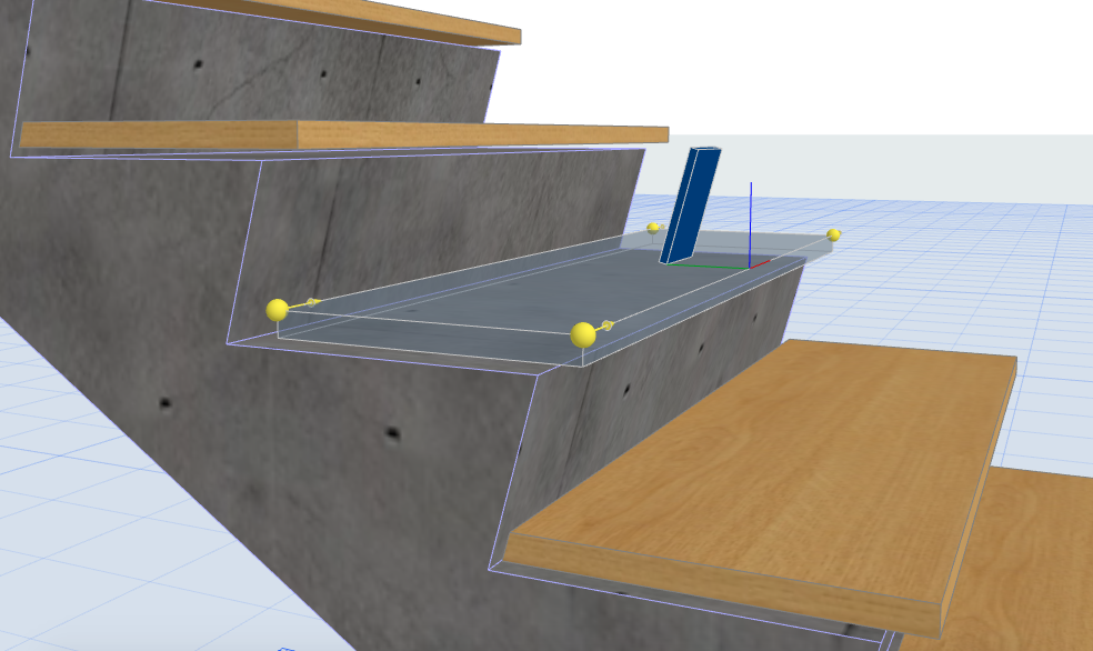
For special geometric cases (Tread Trailing edge cut, nosing, custom Tread element, etc.) the sizes of the connecting Risers can be needed.
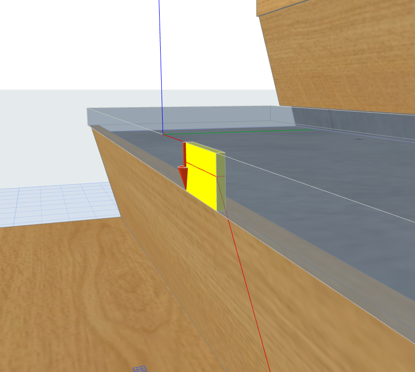
The example object draws a block for the connecting upper Riser using the TREAD_UPPER_RISER_HEIGHT global variable value for its height, and the TREAD_UPPER_RISER_THICKNESS value for its thickness. The block is positioned 0.1 meter in the direction of the Y axis from the Tread coordinate system's origo, and its width is 0.1 meter. The block is rotated around the Tread coordinate system's X axis by the value of the TREAD_UPPER_RISER_SLANT_ANGLE global variable.
For the lower Riser sizes a similar block is used for representation. The block for the lower Riser is positioned under the Tread by the TREAD_THICKNESS global variable value, the TREAD_LOWER_RISER_HEIGHT value is used for its height, the TREAD_LOWER_RISER_THICKNESS value is used for its thickness, its width is 0.1 meter.
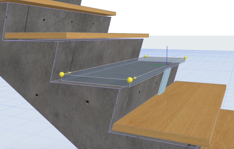
Note that if the Tread nosing value is checked, the lower Riser will be positioned in the direction of the Y axis according to the nosing value.
Nosing methods and values
For a detailed Tread element with nosing the value of the nosing set in the stair tool can be needed. If the Riser is slanted, the nosing value of a Tread can be given in two different methods in ARCHICAD:
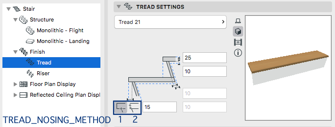
In the examople object the nosing method is represented by an arrow, starting on the X axis of the local coordinate system: the direction of the arrow represents the corresponding method, where the nosing value is measured in that direction.
In case of both methods, the nosing value is represented with a block on the X axis. For its height the value of the TREAD_THICKNESS global variable is used, its width is 0.05 meter. In case the nosing method is set to nosing by value length (TREAD_NOSING_METHOD = 1), the depth of the block equals with the value of the TREAD_NOSING global variable.
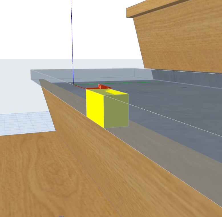
If the nosing method is set to nosing by slanting length (TREAD_NOSING_METHOD = 2), the value of the TREAD_NOSING_BY_SLANTING global variable is the distance of the X axis and the horizontal line on the block. The depth of block is calculated from the slanting length, an extension line in the direction of the slanted riser represents the calculation graphically.