The level of object model display complexity can depend on many things in ARCHICAD:
- display detail level must change according to the scale of the architectural plan type
- different model might be needed for 3D view and for section/elevation (section reveals inner structure as well)
- editing can be made faster with simplified models
- solid element operations need different 3D models than simple 3D views
- listing and scheduling may need different model details
ARCHICAD has supporter features for all these to help the GDL developer to set the perfect model detail level for every context.
For GDL objects, ARCHICAD provides a special set of global variables:
- GLOB_SCALE
- GLOB_VIEW_TYPE
- GLOB_PREVIEW_MODE
- GLOB_FEEDBACK_MODE
- GLOB_SEO_TOOL_MODE
To check all options, please read the listed globals in the GDL Reference Guide, Global Variables section.
Scale Sensitivity
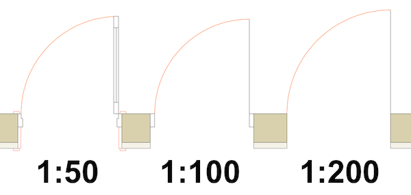
Just take a look at this simple example of the 2D symbol types of a door object in different scales:

The reasons for this is obvious for every architect in the world: printing and country standards.
To make your object behave differently in certain scales or range of scales, use the GLOB_SCALE global variable. It contains the right side value of the scale definition:
if the scale is 1:50 the value stored in GLOB_SCALE is 50.
This value can be used to define separate 2D and 3D (section/elevation, 3D document) models in your scripts.
Example
Object created under Seating subtype. Starting from 1:50 and below, the lines of backrest and armrest are displayed as well (detailed 2D model).
pen gs_cont_pen
fill gs_fill_type

gosub "drawChairPolygon"
if GLOB_SCALE <= 50 then
	! backrest
	line2 0, 9/10*B, A, 9/10*B
	! arms
	line2 9/10*A, 0, 9/10*A, 9/10*B
	line2 1/10*A, 0, 1/10*A, 9/10*B
endif

end

"drawChairPolygon":
	poly2_b 5, 1+2+4,
			gs_fill_pen, gs_back_pen,
			0, 0, 1,
			A, 0, 1,
			A, B, 1,
			0, B, 1,
			0, 0, -1
return
Make sure you keep the display standards of the nation you are developing for in mind when dealing with scale dependent detail levels.
It is well recommended to keep a consistency between the 2D scale sensitive details and the section scale sensitive details in your object. For section context definition, read on.
Model space – Model size
Model elements (LINE2, RECT2, etc.) are always displayed in model size in model space, so the paper size (printed size) of such elements always changes according to the current scale in printing.
If you want to create objects defined with paper size parameters (“Real” type, mm), but using model size based GDL elements, you have to do the following:
- add “Real” type parameters to the object for size parameters
- use these parameters to create model size based variables, manipulating them with the current scale
- use these modified variables in modeling commands
Example
The rectangle (let’s say a frame of a label) having “size1_mm” = 10 mm (Real type), “size2_mm” = 20 mm (Real type) sides should always keep the same size in printing:
_paperToModel = GLOB_SCALE / 1000

_size1_model = size1_mm * _paperToModel
_size2_model = size2_mm * _paperToModel

rect2 0, 0, _size1_model, _size2_model
Try this script, and see what happens if you change the scale. The size of the model is always corrected to keep the printing size unchanged in any scale.
Model space – Paper size
The DEFINE STYLE command for text elements displayed with TEXT2 command are always interpreted in millimeters, so their size is constant on paper (printing), but changing in model space according to the scale automatically.
If you want to fit such text to a model based element (keep the proportion of text display size and object display size), you have to manipulate the size of the text in the style definition according to the current scale.
Example
Displaying a text on a chair symbol (which is in model size). Add text customization parameters to the object (“fontType” – “String” type, “fontSize” – “Real” type).
The text display size (_fontSizeModel) will change according to the current scale to keep the proportions with the model parts.
The parameter “fontSize” is in millimeters. The default auto-conversion of text elements (to keep the text paper size constant) needs to be counteracted, see _fontSizeModel modifications:
rect2 0, 0, A, B
_paperToModel = GLOB_SCALE / 1000
_fontSizeModel = fontSize / _paperToModel
define style "textstyle" fontType, _fontSizeModel, 5, 0
set style "textstyle"
text2 A/2, B/2, "C"
Paper space – Paper size
Annotation elements and included texts should be working in paper space. Use “Real” type parameters (mm or point) to set up these texts. Most GDL text handling commands expect mm as input, so if you have point parameter, convert it to mm first:
dot_in_mm = 25.4 / 72
For more information about text handling, see the following:
Text Handling tutorial
Advanced text handling tutorial
Tips and tricks about texts
Detail level according to usage type
To create a separate model for 3D display and for solid element operations, use the GLOB_SEO_TOOL_MODE global. For example, you create a Towel Dispenser object, which can be inserted into a wall. The normal 3D model is hollow (because you need space for the towels), but if you want to cut a perfect hole in the wall for it, you need a model that is solid:
if GLOB_SEO_TOOL_MODE then
	!script of solid simple model
		prism_ 5,ZZYZX,
		0, 0, 15,
		A, 0, 15,
		A, B, 15,
		0, B, 15,
		0, 0, -1
else
	!script of detailed, hollow model
endif
Think about stairs for other example: you want to cut the slab not only with the stair itself, but the space for people to use the stair. In order to be able to do that, the object needs to define a bigger bulk in the script.
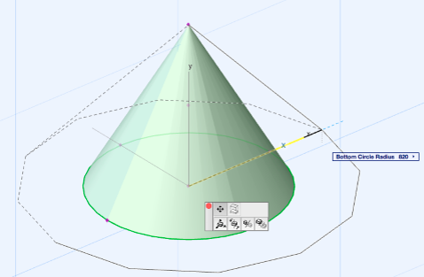
Editing can be made a lot faster, if only the most essential form is displayed in feedback mode.
Feedback mode is corresponded to GDL via GLOB_FEEDBACK_MODE global variable by ARCHICAD.
For example, when the radius parameter of a cone is being edited, there is no need to display high resolution arcs:
if GLOB_FEEDBACK_MODE then
	resol 12
else
	resol gs_resol
endif

To create different models for simple 3D and section, use the GLOB_VIEW_TYPE global (3D – 3, Section – 4). Usually, in 3D the insides of an object is not visible, so it is not necessary to interpret those parts when only looking at the object from the outside. Skip the invisible parts in your scripts, only running them when the object is cut.
GLOB_VIEW_TYPE can also be used to run script parts for calculation models, 3D Documents, 2D, Elevation, Detail and Layout context.
There is a way to distinguish between different preview modes as well: listing needs a special preview model of your object sometimes, and the object settings dialog itself has a preview as well. These are not necessarily the same as the normal 3D model, so don’t be afraid to deal with them using GLOB_PREVIEW_MODE options.
Note: most of these globals are only available starting from ARCHICAD 19. In previous versions, use GLOB_CONTEXT and GLOB_SCALE to cover most of the above usage types.