Doors and Windows are surely the most often represented types of GDL objects, which implies increased quality and optimality requirements.
To achieve this, the GDL developer must follow lots of general instructions, and has to rely on information coming from ARCHICAD a lot more than in case of other object types.
Doors and windows have to work error free in straight, trapeze and curved walls as well.
This lecture covers the basics of how to create a door/window in a straight wall, and the options you have to think about when creating them.
Note: in ARCHICAD, door and window objects include the wallhole as well.
Object types
Wall openings:
Door, Window, Corner window
Other wall connected types:
Wall niche, Chimney, air shaft, Wall end
To decide the type and let ARCHICAD know it, use special subtypes. Using the right subtype will sort your object into the correspoding Tool category, and enables ARCHICAD to use special positioning features on them: they can be only placed in an existing wall.
Subtypes to use:
- for door: Model Element/Opening/Wall Opening/Door (Wall)
- for window: Model Element/Opening/Wall Opening/Window (Wall)
Placing specials
The object itself has a rotated coordinate system in 3D:
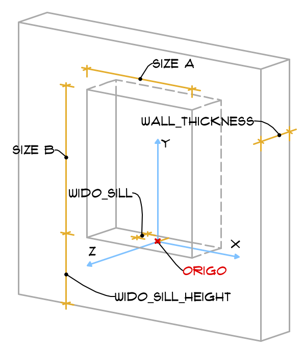
the default position fits the wall, so axes X and Y are parallel to the wall surface, while axis Z is perpendicular to it.
Size “A” is measured on axis X, while size “B” is on the Y axis. The object origo is in the bottom center of the wall opening’s A size, moved on Z axis with sill depth (WIDO_SILL global) value.
This is all very helping when scripting the D/W structure, but gives us some difficulties when dealing with connected structures (such as sunshades, sills, boards etc.)
To check this, create a new window object (watch out for the correct subtype!), and place the following into its 3D script:
! lines to represent coordinate system
! axis X
lin_ 0, 0, 0, 1, 0, 0
! axis Y
lin_ 0, 0, 0, 0, 2, 0
!axis Z
lin_ 0, 0, 0, 0, 0, 3

! blocks to represent coordinate system
pen 58
material 19
block 1, 		0.003,	0.003
block 0.003, 	1,		0.003
block 0.003, 	0.003,	1

! Sill depth representation using WIDO_SILL global
pen 1
material 30
rotx 180
addy -0.003
block 0.003, 	0.003,	WIDO_SILL
del 2
Check out the GDL Manual section about Door and Window objects for more about placing.
Globals of positioning I.
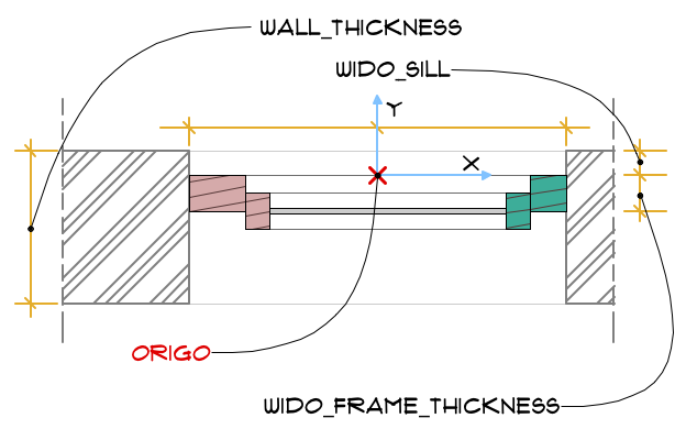
The following globals contain information about the position of a window/door inside a wall:
WIDO_SILL: this is the value set in Reveal Depth parameter.
WIDO_FRAME_THICKNESS: this is the value set in “Nominal Frame Thickness” parameter of the window/door (set in in Details/Compatibility options in GDL Editor).
WALL_THICKNESS: the global contains the full depth value of the wall the window/door is placed into.
Globals of positioning II.
The placing details can be identified by checking the current value of 3 more global variables:
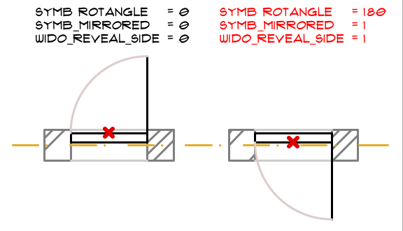
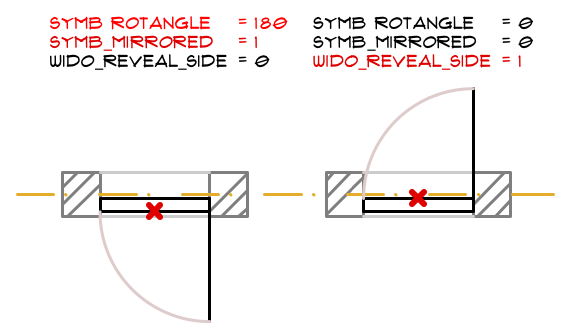
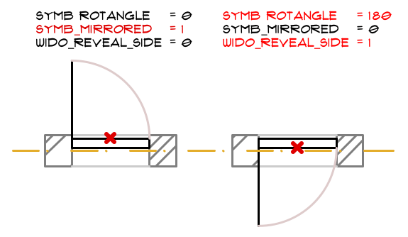
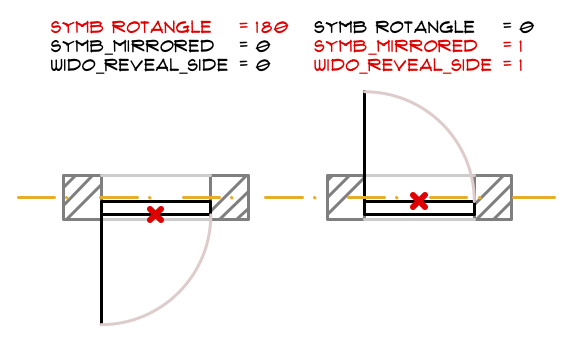
- SYMB_MIRRORED: shows if the object is mirrored to the Y-Z plane in 3D or to the Y axis in 2D
- SYMB_ROTANGLE: shows if the object is “mirrored” by the longitudinal axis of the wall (rotation by 180 degrees)
- WIDO_REVEAL_SIDE: shows if the object is flipped
Flipping
Flipping means turning the window/door inside-out, but keeping its sill depth: the opening-opposite side changes.
ARCHICAD does the following steps when you hit the FLIP button in a door-window object:
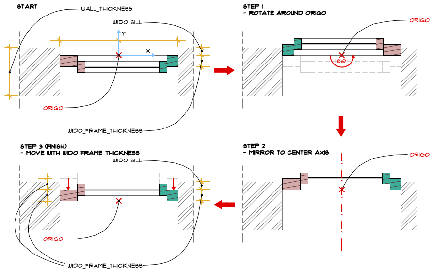
Let’s see all 8 combinations depending on how you clicked the window/door into the wall, or what type of editing happened after placing.

Note: these options should be counteracted when dealing with manufacturer content, since a “real” window can not be mirrored or turned inside-out.
Moreso, there are connecting structure parts of a window/door, which parts should not be moved when the object is flipped:
sill, board, sunshade, casing is not supposed to turn inside out, they should stay on their original wall face.
Creating the 3D model
For the transformation parts of the script, please, open the downloadable example object. Don’t forget to set and use the correct pen and surface parameters before each part in the script. Refer to the subtype parameters, or create attribute parameters of your own. The most simple method is to use a prism with an inside hole for the frame, symmetrical to the bottom centerpoint:pen penCont3D material gs_frame_mat prism_ 10, gs_frame_thk, -A/2, 0, 15, A/2, 0, 15, A/2, B, 15, -A/2, B, 15, -A/2, 0, -1, -A/2 + gs_frame_width, gs_frame_width, 15, A/2 - gs_frame_width, gs_frame_width, 15, A/2 - gs_frame_width, B - gs_frame_width, 15, -A/2 + gs_frame_width, B - gs_frame_width, 15, -A/2 + gs_frame_width, gs_frame_width, -1If you want to add rebate to your object, either use 2 corresponding prisms, or create a “body” for the rebate, and use solid element operations (grouping) to subtract it from the frame prism. The simple sash should be done as the simple frame, but don’t forget to position it first:
pen gs_sash_pen
material gs_sash_mat

_sashLeftX	= -A/2 + gs_frame_width
_sashRightX	= A/2 - gs_frame_width
_sashTop	= B - gs_frame_width
_sashBottom	= gs_frame_width

prism_ 10, gs_sash_thk,
		_sashLeftX,		_sashBottom,	15,
		_sashRightX,		_sashBottom,	15,
		_sashRightX,		_sashTop,	15,
		_sashLeftX,		_sashTop,	15,
		_sashLeftX,		_sashBottom,	-1,
		_sashLeftX + gs_sash_width,	_sashBottom + gs_sash_width,	15,
		_sashRightX - gs_sash_width,	_sashBottom + gs_sash_width,	15,
		_sashRightX - gs_sash_width,	_sashTop - gs_sash_width,	15,
		_sashLeftX + gs_sash_width,	_sashTop - gs_sash_width,	15,
		_sashLeftX + gs_sash_width,	_sashBottom + gs_sash_width,	-1
The hole for the glazing is already cut, all you have to do is fill it up:
pen gs_glass_pen
material gs_glass_mat

_glassLeftX	= -A/2 + gs_frame_width + gs_sash_width
_glassRightX	= A/2 - gs_frame_width - gs_sash_width
_glassTop	= B - gs_frame_width - gs_sash_width
_glassBottom	= gs_frame_width + gs_sash_width

prism_ 5, gs_glass_thk,
		_glassLeftX,	_glassBottom,	15,
		_glassRightX,	_glassBottom,	15,
		_glassRightX,	_glassTop,		15,
		_glassLeftX,	_glassTop,		15,
		_glassLeftX,	_glassBottom,	-1
Enhance your object with editable hotspots for dimensions or opening angle. See the lesson about Hotspots and graphical editing. Use “halfA” parameter if you need center-symmetrical editing. In 3D:
! A bottom part
hotspot 0,		0,	0, _unID, halfA, 1+128	!BASE (hidden)
_unID = _unID + 1

hotspot -1,		0,	0, _unID, halfA, 3	!REFERENCE
_unID = _unID + 1

hotspot halfA,		0,	0, _unID, halfA, 2	!MOVING
_unID = _unID + 1
In Parameter script:
! connect size "A" and "halfA" parameters
if GLOB_MODPAR_NAME = "halfA" then
	A = 2 * halfA
	parameters A = A
else
	halfA = A / 2
	parameters halfA = halfA
endif
Creating the 2D symbol
Make sure you make yourself familiar with the 2D coordinate system first. Use polygons to create the frame, sash and glazing representations, set the matching attributes before drawing each. Either you can work with absolute coordinates for the polygons, or use transformations. If the frame is symmetrical, iterate through the 2 sides:pen gs_pen_2D add2 -A/2, 0 pen cutLinePen _nTrans = 0 for _i = 1 to 2 fill frameFillType poly2_b 5, 1+2+4, frameFillPen, frameFillBgPen, 0, 0, 1, gs_frame_width, 0, 1, gs_frame_width, -gs_frame_thk, 1, 0, -gs_frame_thk, 1, 0, 0, -1 add2 A, 0 mul2 -1, 1 _nTrans = _nTrans + 2 next _i del _nTrans del 1Do the same for the sash polygon as well using sash size parameters, then add the middle glazing part. If sou have missing uncut lines, add them to the symbol with LINE2 commands. Enhance your drawing with editable hotspots for size and 2D opening angle. See the lesson about Hotspots and graphical editing. Tip: use the GLOB_SCALE global to create different detail level symbols for scale intervals.
Parameter script
Make sure all dimensions are set with valid ranges (do not let frame width be zero, etc.). The overall dimensions (“A, “B”) valid range should correspond with the subpart sizes:_minUnitWidth = 2 * gs_frame_width + 2 * gs_sash_width + 0.01 _minUnitHeight = 2 * gs_frame_width + 2 * gs_sash_width + 0.01 values "A" range [_minUnitWidth, ) values "B" range [_minUnitHeight, )Tip: use GLOB_VIEW_TYPE gobal to create different models for 3D, Section/Elevation or 3D document.
