Compatibility: introduced in ARCHICAD 22.
From ARCHICAD 22 new curtain wall representation options has been introduced to the curtain wall components at Model View Options / Curtain Wall Options. This post presents the creation of a curtain wall panel which reacts on the provided detail level options.
MVO Curtain Wall Panel Options
At Model View Options / Curtain Wall Options a checkbox can turn off each component’s visibility, which method is handled by ARCHICAD. The detail level of the curtain wall components should be handled by the library parts, based on the values of the provided Curtain Wall Component global variables.
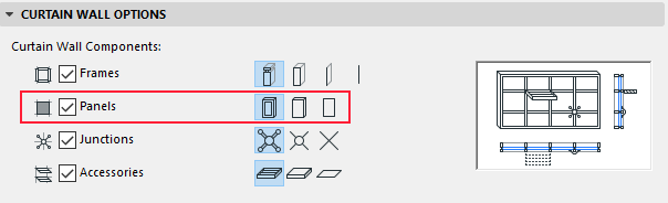
To use this options, you have to work with the GLOB_MVO_CWPANEL_DETLEVEL global variable which values are detailed (4), simplified (3) and schematic (2).
The 3D schematic model
The schematic model can be drawn automatically by ARCHICAD, or can be defined by the panel’s 3D script. You can control this function, by using the AC_AutoSchematicModel boolean parameter. If it is set to 1, ARCHICAD will create the model. This model covers the area defined by the neighbouring frames axis’ and the 3D outline on the curtain wall grid and the surface pen of plane is controlled by the pen set at Curtain Wall System / Floor Plan and Section / Outlines menu as Uncut Line Pen.
If you want to create your own schematic model, set the parameter value to 0. In this case, the library part should draw the Schematic model using its own attribute set. In the following examples this control parameter is turned off in order to provide a comprehensive overview about the MVO sensitivity.
Example for the detail levels
Based on the value of GLOB_MVO_CWPANEL_DETLEVEL, different models should be created for each detail level. This 3D script below results the following models for the MVO detail level settings:
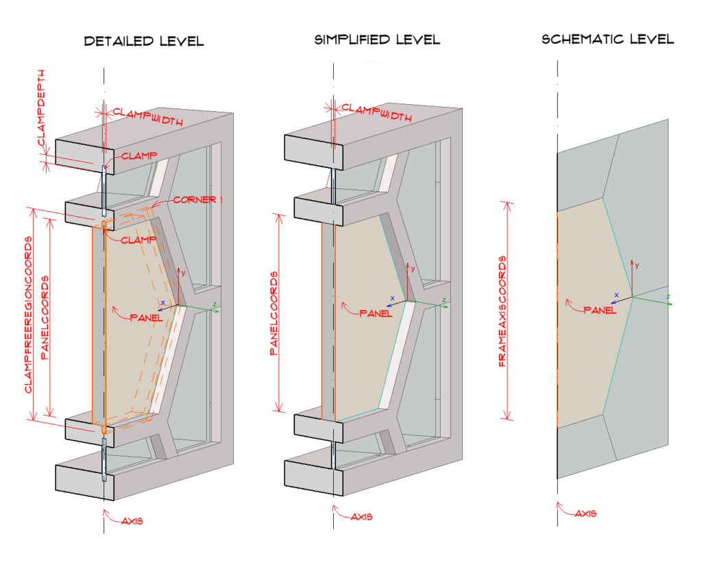
For the detailed panel representation the geometry of the How to create a curtain wall panel? post example is used. For the simplified representation we build a bounding box with the same panel sizes. For schematic representation a plane is created on the axis.
! ====================================================================
! Set constant values and variables
! ====================================================================
! constant values for GLOB_MVO_CWPANEL_DETLEVEL
DETLEVEL3D_SCHEMATIC	= 2
DETLEVEL3D_SIMPLE	= 3
DETLEVEL3D_DETAILED	= 4
The Detailed and the Simple models have dimensions in the X-Y direction of the panel’s local coordinate system. The Schematic models have no dimension in the Z direction, so they should always be positioned on the curtain wall grid.
! initalize variables
    dim _polygonCoords[][2]
    nCorners = vardim1(AC_PanelCoords)

! ====================================================================
! Set attributes
! ====================================================================

building_material bMatPanel
pen penUnCut
sect_attrs{2} penCut

_surface = 1
bSucceed = request{2} ("Building_Material_info", bMatPanel, "gs_bmat_surface", _surface)

! ====================================================================
! Using MVO Settings
! ====================================================================

if GLOB_MVO_CWPANEL_DETLEVEL = DETLEVEL3D_DETAILED then
    ! ====================================================================
    ! Detailed Panel
    ! ====================================================================
    addz ac_clampWidth/2	! stand to the outside of clamp

    ! --- build the outside panel ---------
    _polygonCoords = ac_panelCoords
    gosub "getPolygonCoords_forPrism"

    _thicknessPrism = ac_clampWidth
    gosub "buildPrism"

    ! --- build the inside panel ---------
    addz -ac_clampWidth

    _polygonCoords = ac_clampFreeRegionCoords
    gosub "getPolygonCoords_forPrism"

    _thicknessPrism = thicknessInsideSkin
    gosub "buildPrism"

    del 2
else
    if GLOB_MVO_CWPANEL_DETLEVEL = DETLEVEL3D_SIMPLE then
        ! ====================================================================
        ! Simplified Panel
        ! ====================================================================
        addz ac_clampWidth/2	! stand to the outside of clamp

        _polygonCoords = ac_clampFreeRegionCoords
        gosub "getPolygonCoords_forPrism"

        _thicknessPrism = thicknessInsideSkin + ac_clampWidth
        gosub "buildPrism"
        del 1
    else
        ! ====================================================================
        ! Schematic Panel
        ! ====================================================================
        for i = 1 to nCorners
            put ac_frameAxisCoords[i][1], ac_frameAxisCoords[i][2], 0, 8+1+2+4
        next i

        plane_ nsp/4, get (nsp)
    endif
endif


! ==============================================================================
end ! end ! end ! end ! end ! end ! end ! end ! end ! end ! end ! end ! end !
! ==============================================================================

"getPolygonCoords_forPrism":

    for i = 1 to nCorners
        put _polygonCoords[i][1], _polygonCoords[i][2], 0, 8+1+2+4, _surface
    next i

return

"buildPrism":
    cprism_{3} _surface, _surface, _surface, 1+2+4,
            nsp/5, -_thicknessPrism,
            get(nsp)
return