Forum Replies Created
-
AuthorPosts
-
Barry Kelly
ParticipantThere is probably a HIDEPARAMETERS ALL command in the script.
Comment that out and the parameter list should be visible to the user.Barry.
Versions 6.5 to 22
Dell XPS- i7-6700 @ 3.4Ghz, 16GB ram, GeForce GTX 960 (2GB), Windows 10
Dell Precision M6800 - i7 4700MQ @ 2.40GHz, 16GB RAM, AMD FirePro M6100 (2GB), Windows 7 64bitParticipantThanks Peter.
That is what I thought.
I was just hoping there may be some way to find the current layer combination that I didn’t know about.
It could be a quite handy thing to be able to do.Barry.
Versions 6.5 to 22
Dell XPS- i7-6700 @ 3.4Ghz, 16GB ram, GeForce GTX 960 (2GB), Windows 10
Dell Precision M6800 - i7 4700MQ @ 2.40GHz, 16GB RAM, AMD FirePro M6100 (2GB), Windows 7 64bitParticipantI have no real idea why but it seems to all be working now.
I tried a simple object calling a text macro – that worked.
I found a window and made it call the same text macro – it worked.
I went back to my original window which called its own text macro – it didn’t work.
I noticed the text width was being calculated inside the IF/THEN statement, so I moved it – still didn’t work.I changed the CALL with listed parameters to CALL PARAMETRS ALL – and it worked.
I changed it back and it worked.
It seems that somehow saving the actual window object did the trick – even though I was only making the change in the macro.
But even stranger, all of my other windows are now working and I haven’t re-saved any of them.Anyway, crisis averted.
Barry.
Attachments:
Versions 6.5 to 22
Dell XPS- i7-6700 @ 3.4Ghz, 16GB ram, GeForce GTX 960 (2GB), Windows 10
Dell Precision M6800 - i7 4700MQ @ 2.40GHz, 16GB RAM, AMD FirePro M6100 (2GB), Windows 7 64bitParticipantThe text macro is called from the 2D script of my window object.
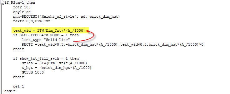
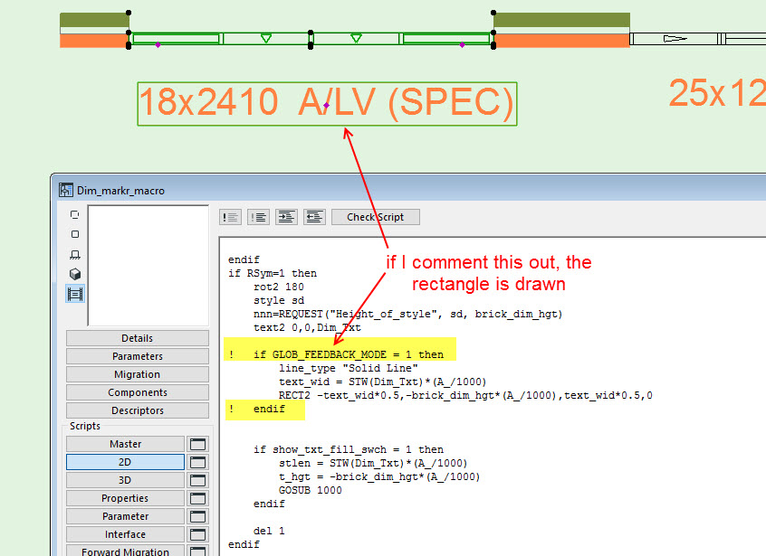
The values of the text to be shown is all sent correctly as the placed window shows the correct text.The text macro is all done in the 2D script.
If I comment out the “IF GLOB_FEEDBACK_MODE = 1” line and just have the rectangle, then that shows on my window in plan.
But I only want the rectangle to show if there is feedback (editing of hotspot).I will see create a simple object that does the same CALL and will see if I can get that to work.
Barry.
Attachments:
Versions 6.5 to 22
Dell XPS- i7-6700 @ 3.4Ghz, 16GB ram, GeForce GTX 960 (2GB), Windows 10
Dell Precision M6800 - i7 4700MQ @ 2.40GHz, 16GB RAM, AMD FirePro M6100 (2GB), Windows 7 64bitMarch 3, 2020 at 10:01 in reply to: Creating a label whose leader sits in the middle of the first row of text #18604ParticipantWe have a tips&tricks document that might help finding the relevant ac_ parameters:
<iframe width=”500″ height=”282″ title=”“New parametrization of labels for ARCHICAD22” — GRAPHISOFT GDL Center” class=”wp-embedded-content” src=”https://gdl.graphisoft.com/tips-and-tricks/new-parametrization-of-labels-for-archicad22/embed#?secret=BUKDkOJvnf” frameborder=”0″ marginwidth=”0″ marginheight=”0″ scrolling=”no” style=”position: absolute; clip: rect(1px, 1px, 1px, 1px);” sandbox=”allow-scripts” data-secret=”BUKDkOJvnf” security=”restricted”></iframe>
And now that needs to be updated for the new connection points in 23.
Barry.
Versions 6.5 to 22
Dell XPS- i7-6700 @ 3.4Ghz, 16GB ram, GeForce GTX 960 (2GB), Windows 10
Dell Precision M6800 - i7 4700MQ @ 2.40GHz, 16GB RAM, AMD FirePro M6100 (2GB), Windows 7 64bitParticipantJust a question, if I need to get coordinate data of any element for my library part, to have the same capacity of the accessories, how should we proceed using GDL ??
This is why we still need the accessory add-ons.
It is these add-ons that form the link between the object and the element (at least that is my understanding).
I would love an add-on for multi-plane roof as I am not skilled enough to create my own.The GDL objects that work with the add-ons don’t need to be maintained by Graphisoft.
But a basic object that reads all of the element parameters would be nice – it doesn’t actually have to do anything.I am sure there are plenty of users that can create new objects.
Even I am currently getting my objects to work with the roof accessory (hence the desire for a multi-plan roof add-on).
If I can do it I am sure there are many others that can do it as well.Barry.
Versions 6.5 to 22
Dell XPS- i7-6700 @ 3.4Ghz, 16GB ram, GeForce GTX 960 (2GB), Windows 10
Dell Precision M6800 - i7 4700MQ @ 2.40GHz, 16GB RAM, AMD FirePro M6100 (2GB), Windows 7 64bitParticipantFrom this you can get the file path and the file name.
You can then amend either/both to get the file path and name you require (merger the strings back together) to create or open the file you want.I do exactly this to save text files with the names I want for quants output in the job folder, or even a sub-folder of that job folder.
Barry.
Versions 6.5 to 22
Dell XPS- i7-6700 @ 3.4Ghz, 16GB ram, GeForce GTX 960 (2GB), Windows 10
Dell Precision M6800 - i7 4700MQ @ 2.40GHz, 16GB RAM, AMD FirePro M6100 (2GB), Windows 7 64bitParticipantrrr=REQUEST ("Name_of_plan", "", pname, pfullname, ppath) print pfullname file_numb = STRSUB(pfullname, 1, 5) print file_numbThis works for me in the master script (also 2D & 3D but not parameter script).
No you can’t save the outcome as a parameter (that would be nice though as we don’t all use modules).
But you can use the outcome and can compere it to your text file number.Barry.
Versions 6.5 to 22
Dell XPS- i7-6700 @ 3.4Ghz, 16GB ram, GeForce GTX 960 (2GB), Windows 10
Dell Precision M6800 - i7 4700MQ @ 2.40GHz, 16GB RAM, AMD FirePro M6100 (2GB), Windows 7 64bitParticipantIf the lines are part of the custom door leaf object, then you would rightly expect them to show for the 2nd door if they work for the first one.
But I am wondering if in the process of mirroring (MUL) and relocating for the 2nd door, the lines are somehow being moved from their original position.Barry.
Versions 6.5 to 22
Dell XPS- i7-6700 @ 3.4Ghz, 16GB ram, GeForce GTX 960 (2GB), Windows 10
Dell Precision M6800 - i7 4700MQ @ 2.40GHz, 16GB RAM, AMD FirePro M6100 (2GB), Windows 7 64bitParticipantI am assuming that swing line is not part of your custom door panel, but created in the door frame object regardless of the door panel used.
If you view the door in 3D and change to wire frame view, is the line there at all.
Maybe hidden inside the door panel thickness?Barry.
Versions 6.5 to 22
Dell XPS- i7-6700 @ 3.4Ghz, 16GB ram, GeForce GTX 960 (2GB), Windows 10
Dell Precision M6800 - i7 4700MQ @ 2.40GHz, 16GB RAM, AMD FirePro M6100 (2GB), Windows 7 64bitParticipantThe REVOLVE{2} will always close the polygon (first to last point).
So of you want the surface back to the rotation axis you need to add a point with a 0 (zero) y-position.i.e.
PUT 0, 0.000, 2, shellSurface,
 0, 0.5*diskWidth, 2, shellSurface,
 0.5*diskHeight, 0.5*diskWidth + lipWidth, 2, shellSurface,
 diskHeight, 0.5*diskWidth, 2, shellSurface,
 diskHeight, 0.000, 2, shellSurface

ADDZ 1
 ROTY -90
 REVOLVE{2} NSP/4, 0, 360, 4*1 + 8*1 + 16*1 + 32*1 + 64*0 + 128*0 + 256*0, shellSurface, GET(NSP)
 DEL 2
Barry.
Versions 6.5 to 22
Dell XPS- i7-6700 @ 3.4Ghz, 16GB ram, GeForce GTX 960 (2GB), Windows 10
Dell Precision M6800 - i7 4700MQ @ 2.40GHz, 16GB RAM, AMD FirePro M6100 (2GB), Windows 7 64bitParticipantIt’s OK, I’ve figured it out
Any hints for those following along?
Barry.
Versions 6.5 to 22
Dell XPS- i7-6700 @ 3.4Ghz, 16GB ram, GeForce GTX 960 (2GB), Windows 10
Dell Precision M6800 - i7 4700MQ @ 2.40GHz, 16GB RAM, AMD FirePro M6100 (2GB), Windows 7 64bitParticipantLayouts don’t actually have a scale.
The drawings you place on the layout do have a scale.
That is why the scale bar needs to be part of the drawing title.
Placing a separate object in the layout will have no relation to the drawing.You could however place the object in the Archicad view.
Then it can read the scale of that view (I do this all the time – never use drawing titles).
That would work unless you are then re-scaling the view in the layout (which in my opinion you shouldn’t be doing).Barry.
Versions 6.5 to 22
Dell XPS- i7-6700 @ 3.4Ghz, 16GB ram, GeForce GTX 960 (2GB), Windows 10
Dell Precision M6800 - i7 4700MQ @ 2.40GHz, 16GB RAM, AMD FirePro M6100 (2GB), Windows 7 64bitParticipantI just had a bit of a Friday afternoon play and it can be done.
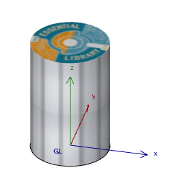
DEFINE TEXTURE 'side' 'Decking 1.jpg',
1,0.75,1,0
DEFINE MATERIAL 'sidematl' 24,
0.9,0.9,0.9, !RGB
0,61,IND(TEXTURE, 'side')

DEFINE TEXTURE 'top' 'Test image.jpg',
1,1,1,0
DEFINE MATERIAL 'topmatl' 24,
0.9,0.9,0.9, !RGB
0,61,IND(TEXTURE, 'top')

BODY -1

CPRISM_ "topmatl", "topmatl", "sidematl",
7, 1.5,
	0.5,       0.0,      11+64,
	0,       0.0,    900,
	   0,          180,   4011+64,
   -0.5,       0.0,      11+64,
	0,       0.0,    900,
	   0,          180,   4011+64,
	0.5,       0.0,     -1

VERT 0.5,0.5,0 !Origin	!!x&y moved 0.5 to centre image
VERT 1.5,0.5,0 !X direction
VERT 0.5,1.5,0 !Y direction
VERT 0.5,0.5,1 !Z direction
COOR 2+256+1024,1,2,3,4

BODY -1
I just used a decking jpg for the bark (so I could see it was straight) and I found a ‘test’ jpg that was round like the rings of a log, as I didn’t have an image of rings to hand.
I used the ‘Box’ wrap method as that seemed to work best for the side texture and moved the origin to centre the circular image.
I wasn’t having much luck using the ‘Cylindrical’ wrap, it always seems to be straight and didn’t radiate from the origin, and then the sides didn’t map nicely either.
Might try again properly later.Barry.
Attachments:
Versions 6.5 to 22
Dell XPS- i7-6700 @ 3.4Ghz, 16GB ram, GeForce GTX 960 (2GB), Windows 10
Dell Precision M6800 - i7 4700MQ @ 2.40GHz, 16GB RAM, AMD FirePro M6100 (2GB), Windows 7 64bitParticipantI can’t say I have tried to make a log with different side and end materials.
If you are not having much luck with the COOR wrapping and projection values or the VERT coordinates, then I would simplify it by having separate (very thin) CPRISMS (or other shapes) ate the ends of the log.
You can then control the materials separately for the ends ant the main log (sides) and may find it a little easier.Barry.
Versions 6.5 to 22
Dell XPS- i7-6700 @ 3.4Ghz, 16GB ram, GeForce GTX 960 (2GB), Windows 10
Dell Precision M6800 - i7 4700MQ @ 2.40GHz, 16GB RAM, AMD FirePro M6100 (2GB), Windows 7 64bit -
AuthorPosts