Forum Replies Created
-
AuthorPosts
-
Peter Koncz
ParticipantDear Aitor Murguzur,
Thank you for the tips, I have found two interesting things we can experiment with.
The Deconstruct Vector command is new, we’ll take a look! I’ll examine the Tube command and make some experiments.
Thanks a lot for the great work and spending your weekend to help us 🙂 Much appreciated!
Peter
BIM manager at Leroy Street Studio, New York, USA
ParticipantThank you for all the replies! I think Gergely has answered my question. IF we want to use a GDL element, we’ll have to come up with a Grasshopper Script that can handle elements with only 1 insertion point…
BIM manager at Leroy Street Studio, New York, USA
ParticipantHi Gergely,
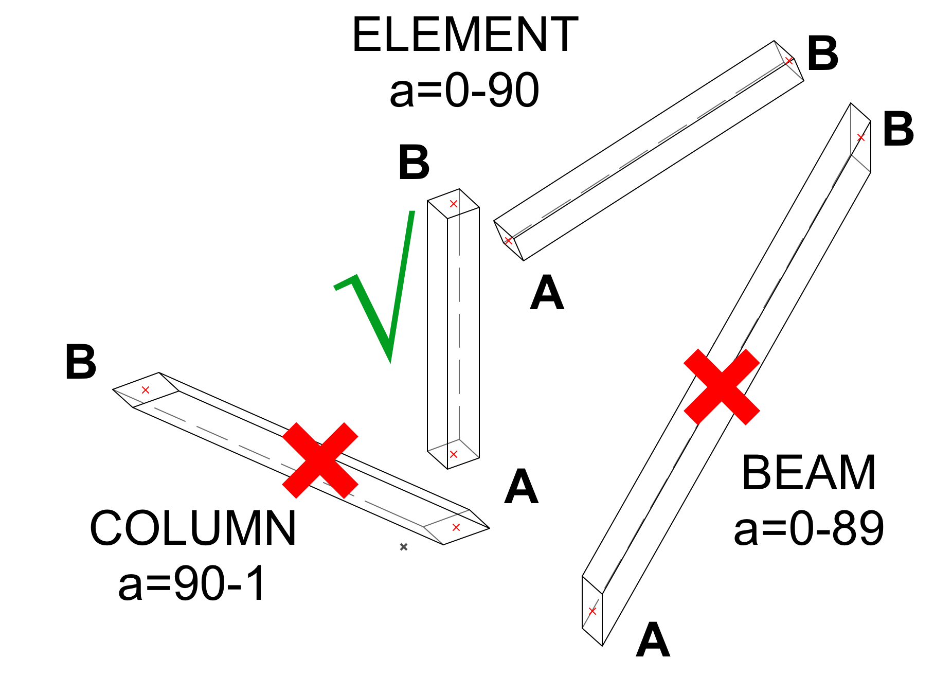
Please, find an image to explain the desired object. It would be a generic structural element, that could use 2 points in space as an input. Both Column and Beam tool can be used, but their angle (a) is limited for both. It means the grasshopper script of the facede has to be split into 2 parts and that is a bit inconvenient. We want a single element without a distortion at the bottom.
I have used the EXTRUDE command, my colleague recommended PRISM, but both use 1 point and vector/length instead of 2 points in space.
roty -90
roty RtYC=ZZYZX
EXTRUDE 4, 0, 0, C, 1 + 2 + 4 + 16 + 32 + 64 + 128,
-A/2, B/2, 0,
A/2, B/2, 0,
A/2, -B/2, 0,
-A/2, -B/2, 0del top
end
The logic of the Grasshopper script does not allow this kind of input. We need to use 2 points as input.
I thought it would be easy to make with GDL, but haven’t found the right command yet. I hope you can help.
Thanks,
PeterAttachments:
BIM manager at Leroy Street Studio, New York, USA
ParticipantBTW, I have also created 2D symbols for the user to comply with Hong Kong standards.
Can you help me how to add a fill to the rectangle symbol?
Attachments:
BIM manager at Leroy Street Studio, New York, USA
ParticipantFinally I have figured out and able to set model size and paper size using SET STYLE, DEFINE STYLE and TEXT2 commands.
I have uploaded the GSM files, you can take a look, if you have time. Thanks,
Attachments:
BIM manager at Leroy Street Studio, New York, USA
ParticipantGuys, I have created this simple door marker, but I cannot get the text size defined… It stays the default 500mm.
Thanks,
BIM manager at Leroy Street Studio, New York, USA
-
AuthorPosts