Compatibility: introduced in ARCHICAD 23.
Opening Symbols can be used with the Opening tool, to show a symbolic representation of the hole. Library parts of subtype Documentation Element / Drawing Symbol / Opening Symbol are listed in the settings dialog for the user to choose from.
Let’s see what data ARCHICAD sends to GDL by creating a symbol that shows a slab opening contour reduced by a margin, allowing the user to measure the net size, taking building tolerances into account.
NOTE: Openings can be placed in Walls, Slabs, Beams, Meshes. The library part doesn’t know anything about the host element, so our example might not make sense as a wall opening. Such constraints can be reflected in the name of the element, or on its preview picture.
Bounding box
The general dimension parameters “A” and “B” are not set for an Opening Symbol. Instead the global variable OPENING_SYMBOL_GEOMETRY.boundingBox2D can be used. Let’s draw a shrunk boundingbox:
margin = 0.05

dict bb : bb = OPENING_SYMBOL_GEOMETRY.boundingBox2D

rect2 bb.xmin + margin, bb.ymin + margin, bb.xmax - margin, bb.ymax - margin

line2 bb.xmin + margin, bb.ymin + margin, bb.xmax - margin, bb.ymax - margin
line2 bb.xmin + margin, bb.ymax - margin, bb.xmax - margin, bb.ymin + margin
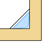
Place an opening into a slab, and select this library part for the uncut symbol. If you move the opening halfway out of the slab, the bounding box will be cut to be within the boundary of the host element. If you rotate the opening, the symbol will rotate with it: the coordinate system is transformed with the opening, with one exception: SYMB_MIRRORED is 0 even if the opening is mirrored.
! continued from above...

add2 bb.xmin + margin / 2,
     bb.ymin + margin / 2

pen 6: line2 0,0, 1,0	! blue x
pen 8: line2 0,0, 0,1	! red  y

del 1
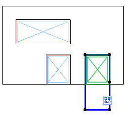
Bounding box and coordinate system of opening symbols
NOTE: The shrunk corners can be easily dimensioned – however these aren’t associative dimensions. Because of technical limitations, hotspots, hotlines and hotarcs from the library part aren’t shown, but all of its lines, arcs and fills are treated as hot elements.
Contour polygon
The solution above is usable only for rectangular openings: change to opening shape to Circular to see what happens. The bounding box will still be a box around the circle, our drawing will be cropped at the edge of the opening. This cropping is an automatic ARCHICAD feature.
NOTE: For debugging purposes, the drawing outside the contour can be shown: select Library Part Diagnostic Mode in the Library Developer menu – you might have to add it first to the menubar in Options / Work Environment. The state of this option is given in the global variable GLOB_DIAGNOSTICS_MODE.
So instead of the bounding box, let’s draw the polygon using the OPENING_SYMBOL_GEOMETRY.polygon2D global variable.
This lists the edges of the contour in a format similar to what the PolyOperations add-on uses: each edge defined by the beginning point, and the (signed) central angle of the arc if the edge is arced.
Draw the contour treating arcs as straight lines for now:
dict contour : contour = OPENING_SYMBOL_GEOMETRY.polygon2D.contour

nEdges = vardim1(contour.edges)
for i = 1 to nEdges

    ! the last edge is included only with its beginning point,
    ! connect it to the first one
    iNext = i % nEdges + 1

    dict _from : _from = contour.edges[i    ].begPoint
    dict _to   : _to   = contour.edges[iNext].begPoint

    line2 _from.x, _from.y, _to.x, _to.y

next i
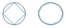
Edges of a circle and an ellipse
Let’s shrink the contour around the centerpoint of the boundingbox (code from the above example is greyed):
margin = 0.05

dict bb : bb = OPENING_SYMBOL_GEOMETRY.boundingBox2D

dict center
center.x = (bb.xmin + bb.xmax) / 2
center.y = (bb.ymin + bb.ymax) / 2

! shrink around center
add2 center.x, center.y
mul2 1 - 2 * margin / (bb.xmax - bb.xmin),
     1 - 2 * margin / (bb.ymax - bb.ymin)

! draw contour
dict contour : contour = OPENING_SYMBOL_GEOMETRY.polygon2D.contour

nEdges = vardim1(contour.edges)
for i = 1 to nEdges

    ! the last edge is included only with its beginning point,
    ! connect it to the first one
    iNext = i % nEdges + 1

    dict _from : _from = contour.edges[i    ].begPoint
    dict _to   : _to   = contour.edges[iNext].begPoint

    ! draw relative to _center
    line2 _from.x - center.x, _from.y - center.y,
          _to.x   - center.x, _to.y   - center.y

next i

del 2
Curved edges
Now convert the arcs in the contour to a format that GDL can draw.
There are no GDL commands that can draw an arc between two end coordinates, even the additional status codes of polygon commands can’t do that without knowing the centerpoint, so we have to calculate it.

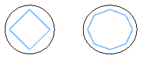
Polygons with a curved edge with different central angles
Since we have a closed contour, it can be drawn as a polygon. The macro “ProfileConverter” does the conversion from a PolyOperations-style polygon to a status-coded one and vice versa.
NOTE: It doesn’t handle all additional status codes, just 3000, 4000 and 900. Feel free to save a copy of this macro with a different name, and use the copy in scripts if you need to modify it.
margin = 0.05

dict bb : bb = OPENING_SYMBOL_GEOMETRY.boundingBox2D

dict center
center.x = (bb.xmin + bb.xmax) / 2
center.y = (bb.ymin + bb.ymax) / 2

! shrink around center
add2 center.x, center.y
mul2 1 - 2 * margin / (bb.xmax - bb.xmin),
     1 - 2 * margin / (bb.ymax - bb.ymin)

! offset contour, so the origin is the center
dict polygon
polygon = OPENING_SYMBOL_GEOMETRY.polygon2D    ! copy whole polygon

nEdges = vardim1(polygon.contour.edges)
for i = 1 to nEdges

    polygon.contour.edges[i].begPoint.x = polygon.contour.edges[i].begPoint.x - center.x
    polygon.contour.edges[i].begPoint.y = polygon.contour.edges[i].begPoint.y - center.y

next i

! conversion to status-coded polygon
dim outflat[]                   ! declare returned array
polygon.hasClosingPoint = 0     ! OPENING_SYMBOL_GEOMETRY.polygon2D is always given
                                !    without repeating the first point
call "ProfileConverter" parameters  bProfileToPolyOp    = 0,
                                    bPolyOpDict         = 1,
                                    PolyOpPolygon       = polygon,
                                    returned_parameters nOut,
                                                        outflat

! put results
for i = 1 to nOut - 1           ! without closing point

    k = (i - 1) * 3
    put outflat[k + 1],         ! x
        outflat[k + 2],         ! y
        outflat[k + 3] + 1      ! status

next i

! draw polygon
toler 0.001	    ! because of mul2 high-density segmentation of arcs is needed
                    !    (distorted to ellipse)
pen iPen
fill iFill
poly2_b NSP / 3, 1 + 2 + 4,
    iPen, 0,
    get(NSP)

del 2
Working with PolyOperations
The previous example doesn’t work well with polygonal and concave contours – try rotating a rectangle by 45° and moving it over the corner of a slab.
We need to use the PolyOperations add-on to properly shrink the contour.
Starting from ARCHICAD23, this is less complex than previously: PolyOperations can handle polygons/polylines given in a dictionary format almost similar to OPENING_SYMBOL_GEOMETRY.polygon2D. One pair of function calls and one variable is enough to store and read the geometry: “StoreDictPolygon” and “GetDestinationDictPolygon”.
Initializing PolyOperations is the same as before:
poChannel = initaddonscope ("PolyOperations", "", "")
preparefunction poChannel, "CreateContainer",         "inputContainer", ""
preparefunction poChannel, "SetSourceContainer",      "inputContainer", ""
preparefunction poChannel, "CreateContainer",         "resultContainer", ""
preparefunction poChannel, "SetDestinationContainer", "resultContainer", ""
Initialize and store the polygon:
dict contourPoly : contourPoly = OPENING_SYMBOL_GEOMETRY.polygon2D    ! copy whole polygon
! tell PolyOperations to work without edgeInfo
contourPoly.useEdgeInfo = 0
preparefunction poChannel, "StoreDictPolygon", "contour", contourPoly
Do the polygon operation:
margin = 0.05
preparefunction poChannel, "OffsetParams", "", 1, -margin
dim resultIDs[]
nResult = callfunction (poChannel, "ResizeContour", "contour", resultIDs)
Theoretically the result of a “ResizeContour” operation can be zero or multiple polygons: 0 if the polygon is shrunk to a line/point, multiple if there is self-intersection. Results have to be read and drawn in a loop:
for iResult = 1 to nResult

    dict polygon
    nVertices = callfunction(poChannel, "GetDestinationDictPolygon", resultIDs[iResult], polygon)
    gosub "drawPolyOpPolygon"

next iResult
Finishing up the example:
closeaddonscope poChannel

end

"drawPolyOpPolygon":
    ! this code is similar to the previous example
    ...
return
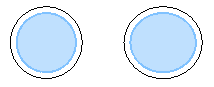
NOTE: Even PolyOperations has some limits, some complex polygons with curved edges can’t be shrunk all the way to a single point. Draw a fill on the floor plan and select “Offset all edges” from the pet palette to see what happens.
![]()
View-dependency
One more thing to know – OPENING_SYMBOL_DISPLAY contains the visibility of the symbol:
- 1: Visible (cut in walls or viewed from above)
- 2: Hidden (hidden, below Floor Plan Cut Plane)
- 3: Overhead (hidden, above Floor Plan Cut Plan)
This allows to use different attributes for each position, while the projected geometry is the same.