Home › Forums › Problems and solutions in GDL › 3D modelling › Beam/Column universal object
Tagged: column beam structure
- This topic has 13 replies, 4 voices, and was last updated 9 years ago by
aitor Leceta.
-
AuthorPosts
-
-
March 16, 2017 at 09:17 #3116
Peter Koncz
ParticipantHi Guys,
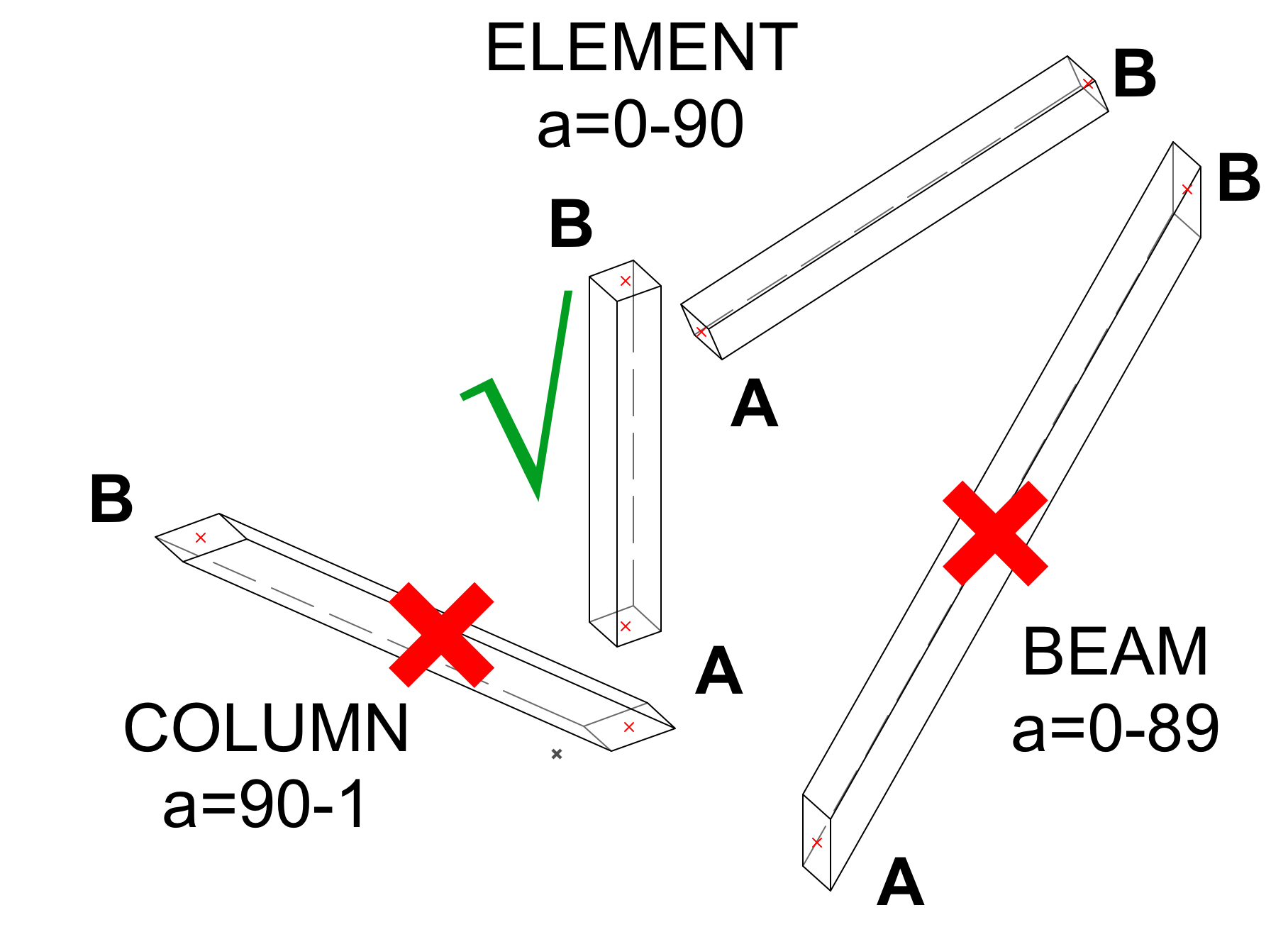
We are working on a Grasshopper-ARCHICAD model where a universal structural element would be very handy. The aim is to generate an element that connects two points in space, but be able to adjust the slanting from 0-90 degrees. The whole element should rotate, we don’t want flat bottoms. Columns at very low angles produce a big spike due to their flat bottom plane.
We have started with BLOCK then switched to EXTRUDE command, but none of them is exactly what we need. Any suggestions?
Peter
BIM manager at Leroy Street Studio, New York, USA
-
March 20, 2017 at 17:56 #3117
Gergely Fehér
KeymasterIt’s not clear for me, what you exactly need… Connecting two points can be done with many commands. Can you post an image about the goal?
Gergely Fehér
Team Leader, Library Team
GRAPHISOFT SE-
March 21, 2017 at 05:02 #3118Participant
Hi Gergely,
Please, find an image to explain the desired object. It would be a generic structural element, that could use 2 points in space as an input. Both Column and Beam tool can be used, but their angle (a) is limited for both. It means the grasshopper script of the facede has to be split into 2 parts and that is a bit inconvenient. We want a single element without a distortion at the bottom.
I have used the EXTRUDE command, my colleague recommended PRISM, but both use 1 point and vector/length instead of 2 points in space.
roty -90
roty RtYC=ZZYZX
EXTRUDE 4, 0, 0, C, 1 + 2 + 4 + 16 + 32 + 64 + 128,
-A/2, B/2, 0,
A/2, B/2, 0,
A/2, -B/2, 0,
-A/2, -B/2, 0del top
end
The logic of the Grasshopper script does not allow this kind of input. We need to use 2 points as input.
I thought it would be easy to make with GDL, but haven’t found the right command yet. I hope you can help.
Thanks,
PeterAttachments:
BIM manager at Leroy Street Studio, New York, USA
-
March 21, 2017 at 19:17 #3121Keymaster
All GDL objects have only one anchor/insertion point – there is no way to have more.
Gergely Fehér
Team Leader, Library Team
GRAPHISOFT SE
-
-
March 21, 2017 at 09:58 #3120
Barry Kelly
ParticipantI’m not quite sure if I follow exactly what you need but TUBE allows you to extrude a polygon along a path of two (or more) points.
You need two extra ‘dummy’ points in the path for the start and end points.
These are used to start and end the path and control the angle of the end surfaces of the extruded (or swept) polygon.
If all the points are perfectly in line then the ends will be perpendicular to that line.
If not in line then the end surfaces will bisect the angle formed by the first 3 and last 3 points in that path (i.e. points 1,2 & 3 and points 2,3,& 4 if you only have a total of 4 points in the path (2 dummy and 2 real)).Barry.
Versions 6.5 to 22
Dell XPS- i7-6700 @ 3.4Ghz, 16GB ram, GeForce GTX 960 (2GB), Windows 10
Dell Precision M6800 - i7 4700MQ @ 2.40GHz, 16GB RAM, AMD FirePro M6100 (2GB), Windows 7 64bit-
March 21, 2017 at 22:26 #3123
aitor Leceta
Participanthi,
as Barry says, I think that TUBE is the best command for this work. SWEEP would also be useful, as long as you could modify your structural elements sections along the directrix path, rotating and/or scaling them.
-
-
March 22, 2017 at 03:07 #3124Participant
Thank you for all the replies! I think Gergely has answered my question. IF we want to use a GDL element, we’ll have to come up with a Grasshopper Script that can handle elements with only 1 insertion point…
BIM manager at Leroy Street Studio, New York, USA
-
March 22, 2017 at 20:33 #3136Participant
ok, I guess I had misunderstood your problem.
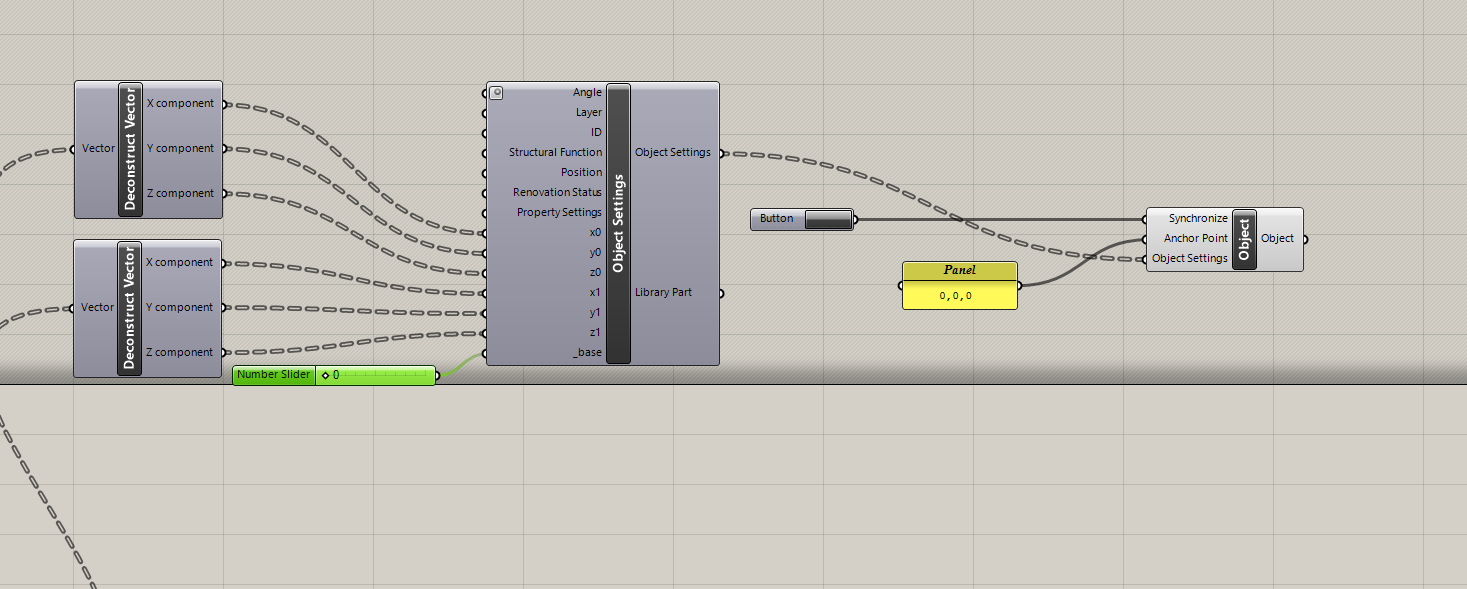
But the fact is that you actually can input multiple points to a GDL object with GH connection, independently of the object insertion point. You should use as parameter the coordinates of your sweeping path, in your case two points (x0,y0,z0 and x1,y1,z0)
then, use this object in GH, expose those coordinates parameters and feed them via your GH definition.
Let’s see if I take some time this weekend to demonstrate this graphically.
-
-
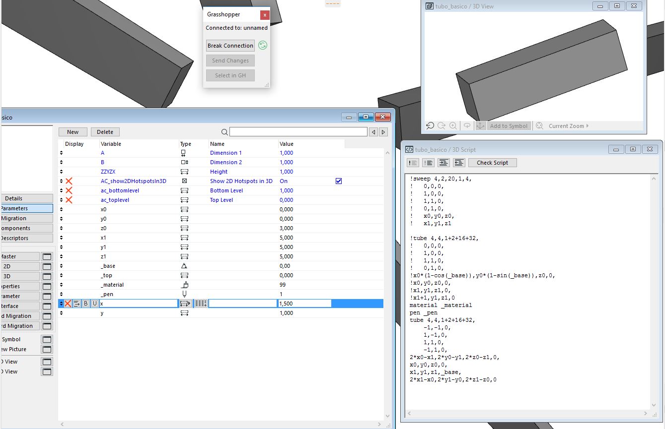
March 26, 2017 at 16:40 #3150Participant
a quick exercise…
Attachments:
-
March 26, 2017 at 16:41 #3153Participant
…
Attachments:
-
March 27, 2017 at 05:19 #3156Participant
Dear Aitor Murguzur,
Thank you for the tips, I have found two interesting things we can experiment with.
The Deconstruct Vector command is new, we’ll take a look! I’ll examine the Tube command and make some experiments.
Thanks a lot for the great work and spending your weekend to help us 🙂 Much appreciated!
Peter
BIM manager at Leroy Street Studio, New York, USA
-
March 27, 2017 at 09:20 #3158Participant
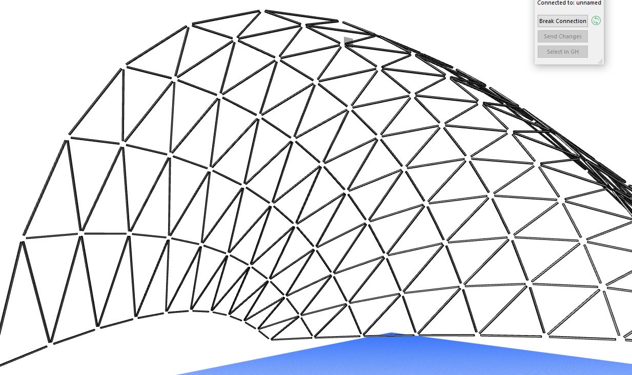
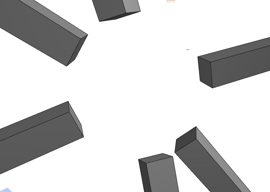
the idea was to illustrate that it’s possible to place objects wichs position is somewhat independent of its insertion point. In this case, all the bar´s insertion point`s are at the origin point.
-
March 27, 2017 at 11:04 #3159Keymaster
It is possible to create objects like this, but it is quite dangerous: as there are many methods in ARCHICAD which uses the insertion point and the objects A-B-ZZYZX dimensions as a bounding box, these object will fail. For example: marquee and limited sections won’t show these objects normally, if the insertion points and the bounding box calculated from their parameters are out of the current range.
Gergely Fehér
Team Leader, Library Team
GRAPHISOFT SE
-
-
March 27, 2017 at 11:23 #3160Participant
oh, I didn’t know that. Something to take into account!
it is a pity since this limits the usability of GDL objects controlled with grasshopper.
thanks!
-
-
AuthorPosts
- The forum ‘3D modelling’ is closed to new topics and replies.