Home › Forums › Problems and solutions in GDL › 3D modelling › Cylinder texture alignment
- This topic has 4 replies, 3 voices, and was last updated 6 years, 4 months ago by
James Murray.
-
AuthorPosts
-
-
November 21, 2019 at 15:49 #18448
James Murray
ParticipantI am building a model of a log with a round CPRISM_, centered on the local origin. I have two surface parameters, one for the sides (bark), and one for the ends (a cut log image). I would like to control the alignment of the end surface texture so the center of the log image is (roughly) centered in the circle. I am using COOR{3} to get the bark going the right way, but I’m having trouble with the ends. Any ideas? Thanks.
James M
-
November 22, 2019 at 02:25 #18449
Barry Kelly
ParticipantI can’t say I have tried to make a log with different side and end materials.
If you are not having much luck with the COOR wrapping and projection values or the VERT coordinates, then I would simplify it by having separate (very thin) CPRISMS (or other shapes) ate the ends of the log.
You can then control the materials separately for the ends ant the main log (sides) and may find it a little easier.Barry.
Versions 6.5 to 22
Dell XPS- i7-6700 @ 3.4Ghz, 16GB ram, GeForce GTX 960 (2GB), Windows 10
Dell Precision M6800 - i7 4700MQ @ 2.40GHz, 16GB RAM, AMD FirePro M6100 (2GB), Windows 7 64bit -
November 22, 2019 at 08:41 #18450
Péter Baksa
KeymasterHi,
There is some information about texture mapping here, does it help you?
Péter Baksa
Library Platform, Software Engineer
GRAPHISOFT SE -
November 22, 2019 at 09:34 #18451Participant
I just had a bit of a Friday afternoon play and it can be done.
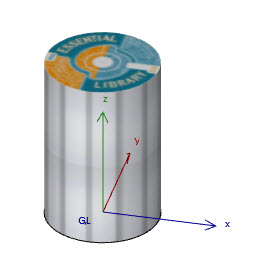
DEFINE TEXTURE 'side' 'Decking 1.jpg',
1,0.75,1,0
DEFINE MATERIAL 'sidematl' 24,
0.9,0.9,0.9, !RGB
0,61,IND(TEXTURE, 'side')

DEFINE TEXTURE 'top' 'Test image.jpg',
1,1,1,0
DEFINE MATERIAL 'topmatl' 24,
0.9,0.9,0.9, !RGB
0,61,IND(TEXTURE, 'top')

BODY -1

CPRISM_ "topmatl", "topmatl", "sidematl",
7, 1.5,
	0.5,       0.0,      11+64,
	0,       0.0,    900,
	   0,          180,   4011+64,
   -0.5,       0.0,      11+64,
	0,       0.0,    900,
	   0,          180,   4011+64,
	0.5,       0.0,     -1

VERT 0.5,0.5,0 !Origin	!!x&y moved 0.5 to centre image
VERT 1.5,0.5,0 !X direction
VERT 0.5,1.5,0 !Y direction
VERT 0.5,0.5,1 !Z direction
COOR 2+256+1024,1,2,3,4

BODY -1
I just used a decking jpg for the bark (so I could see it was straight) and I found a ‘test’ jpg that was round like the rings of a log, as I didn’t have an image of rings to hand.
I used the ‘Box’ wrap method as that seemed to work best for the side texture and moved the origin to centre the circular image.
I wasn’t having much luck using the ‘Cylindrical’ wrap, it always seems to be straight and didn’t radiate from the origin, and then the sides didn’t map nicely either.
Might try again properly later.Barry.
Attachments:
Versions 6.5 to 22
Dell XPS- i7-6700 @ 3.4Ghz, 16GB ram, GeForce GTX 960 (2GB), Windows 10
Dell Precision M6800 - i7 4700MQ @ 2.40GHz, 16GB RAM, AMD FirePro M6100 (2GB), Windows 7 64bit -
November 22, 2019 at 23:20 #18455Participant
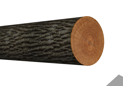
Thanks, Barry, that got me on the right track. The quote unquote cylindrical mapping was ironically not helping.
Attachments:
James M
-
-
AuthorPosts
- The forum ‘3D modelling’ is closed to new topics and replies.