GDL warnings
Like any other programming language, GDL has syntax and logic to be followed. If there is a mistake in syntax, the programmer gets an error message. If there is something confusing, or some unexpected thing happens when running the script, a GDL warning is sent out.
You can choose WHERE you want to send these messages in Options/Work Environment/Model Rebuild Options:
- Interrupt with error messages: a dialog pops up at every problem
- Write Report: the message is written in the Report window
You can choose WHAT you want to send out as a message: this setting is available in the Library Developer menu, called “Check Library Part Scripts for Warnings“. When enabled, not only errors but warnings get reported as well according to the WHERE settings.
You can also choose WHEN you want to see warning messages. This can be set in the Library Developer menu as well, called “Always Send GDL Messages“. Turning this feature on, each time GDL is executed, warnings, errors and print messages get reported. Leaving it off, errors and warnings are only reported at script check/save object, print messages are only shown for object previews.
Note, that using some combinations of the above switches can result in difficulties: for example, having the “Always Send GDL Messages” and the “Interrupt with error messages” enabled together may prevent the execution of something as “simple” as moving an editable hotspot, popping up dialogs all the time.
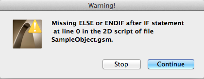
Pressing “Check script” in the library part editor, if there is a problem with your script using the current parameter settings, you will always get a warning or error message popup window. Using the PRINT command, or the GDL debugger may help a lot locating mistakes hard to find otherwise. Note that the line numbers in the GDL warnings refer to the script which contains the problem. Parsing errors must be handled with extra care. These denote the first line in which the parsing gets impossible but the actual problems may be some lines before.
Example
The interpreter detects the missing statement first at the endif and stops there; though the problem is obviously around line 4 where an endif is really missing.
if condition1 then
    if condition2 then
        ! do something

    ! do something - BUT WE MISSED AN 'endif'
else
    ! a potentially long code block
endif
Here are some examples of the latest warning messages developed, with some explanation:
| Warning message | Possible explanation |
| Simple parameter redeclared as an array | specifying a simple parameter in an object and using it as an array in the called macro |
| Undefined parentId “id” used in UI_PAGE definition | missing parent ID in tabpage hierarchy |
| View/Project dependent global “globalName” used in parameter script | see the section called “Global Variables” |
| Request “requestName” used in parameter script | see the section called “REQUEST Options” |
| Application query “applicationQueryName” used in parameter script | see the section called “Application Query Options” |
| Possibly unwanted parameter type change | a parameter receives a value not supported by its original type |
Hotspot and Hotline IDs
Purpose of hotspot/hotline/hotarc identification
In Archicad the hotspot/hotline/hotarc identification is introduced to support associative dimensioning in section. Via this feature a dimensioning item can refer to any of a GDL object’s hotspots/hotlines. It will become an important issue when the number of hotspots/hotlines changes between the object’s different parameterization states.
Problem of old-school hotspots/hotlines
If the programmer doesn’t specify hotspot/hotline/hotarc IDs – or if he sets them to 0 – Archicad will assign continuously increasing ordinal numbers. This solution is correct for static objects but causes dimensioning problems when some hotspots/hotlines appear or hide between parameter set-ups. Namely, the IDs will be rearranged so they will change, and the associative dimensioning items – in section – will go astray.
Editable hotspots
Since Archicad 8 release you can use editable hotspots in your library parts.
The feature is described in Chapter 6, Graphical Editing Using Hotspots except for one possibility.
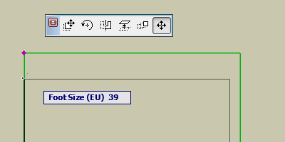
In some cases you may want to display a different parameter from the edited one. See the example code below:
Editable hotspot example – Shoe / Shoe-rack
We want to have the size of a shoe in meters and in shoe sizes, too. For that we create two parameters and connect them in the parameter script. Naturally, the type of the explaining parameter can be different (e.g. text). We emphasize that the edited parameter is footLengthall the way, footSizeEU – the displayed parameter – must be updated via the parameter script.
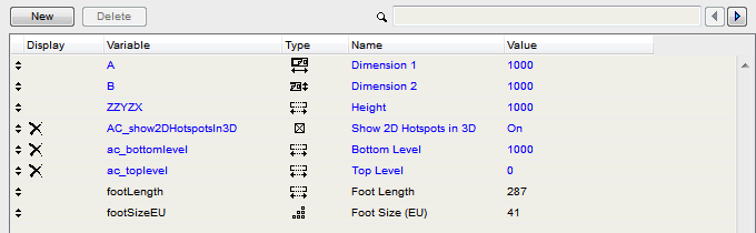
dim _lengthValues[10]
dim _sizeValues[10]
for i = 1 to 10
    _sizeValues[i] = i + 35
    _lengthValues[i] = (i + 35) * 0.007
next i
values "footLength" _lengthValues
values "footSizeEU" _sizeValues

if GLOB_MODPAR_NAME = "footLength" then
    parameters footSizeEU = round_int (footLength / 0.007)
else
    if GLOB_MODPAR_NAME = "footSizeEU" | GLOB_MODPAR_NAME = "" then
        parameters footLength = footSizeEU * 0.007
    endif
endif
rect2 0, 0, footLength * 0.4, footLength   ! or a more realistic shoe model

hotspot2 0, 0,          1, footLength, 1 + 256, footSizeEU
hotspot2 0, footLength, 2, footLength, 2, footSizeEU
hotspot2 0, -0.1,       3, footLength, 3
GDL execution contexts
Archicad lets the GDL object know about the context it is being displayed or used in. The next global variables are used for this purpose:
- GLOB_VIEW_TYPE to determine the active view
- GLOB_PREVIEW_MODE to determine the active preview
- GLOB_FEEDBACK_MODE for editing context indication
- GLOB_SEO_TOOL_MODE for solid element operations context indication
For the possible values refer the section called “General environment information” and the following list:
GLOB_VIEW_TYPE = 2 – 2D, floor plan
The model is displayed in the standard 2D floor plan. In a 3D script this means that the model is projected to 2D via the project2 command. This is the main use of an object – this 2D model must be always correct and efficient.
If GLOB_FEEDBACK_MODE = 1 then the model is displayed via feedback lines on the 2D floor plan during the hotspot editing of the object. This model is drawn many times in a single second throughout the user interaction. This implies that the model should represent the essential parts of the object only. Note, that texts (generated by text2 command) are not refreshed in feedback mode – since it would slow down the output.
GLOB_VIEW_TYPE = 3 – 3D view
The 3D model is displayed in the standard 3D model window or it is the source of photorealistic rendering. This view should omit internal details of the object, since these cannot be seen anyway. This is the second most important use of an object – the 3D model must be always correct and efficient. This target type demands correct outside look.
If GLOB_FEEDBACK_MODE = 1 then the 3D model is displayed via feedback lines in the 3D model window during the hotspot editing of the object. This model is drawn many times in a single second throughout the user interaction. This implies that the model should represent the essential and visible parts of the object only.
GLOB_VIEW_TYPE = 4 – section or GLOB_VIEW_TYPE = 5 – elevation
The 3D model is displayed in a section/elevation window. For these views, the object should generate internal details which are unnecessary for every other view type.
If GLOB_FEEDBACK_MODE = 1 then the 3D model is displayed via feedback lines in a section/elevation window during the hotspot editing of the object. This model is drawn many times in a single second throughout the user interaction. This implies that the model should represent the essential and visible parts of the object only.
GLOB_VIEW_TYPE = 6 – 3D document
The 3D model is displayed in an axonometric window as a drawing. This is used for documentation, dimensioning in 3D.
GLOB_VIEW_TYPE = 7 – detail drawing
The model is used in a detailed drawing window. The model can be more detailed than in other views consequently. The 2D and 3D models are not distinguished – that information can be derived from the script type.
GLOB_VIEW_TYPE = 8 – layout
The model is used in a layout window, with its print display. The model should show its printing look. The 2D and 3D models are not distinguished – that information can be derived from the script type.
If GLOB_FEEDBACK_MODE = 1 then the model is displayed via feedback lines in a layout window during the hotspot editing of the object. This model is drawn many times in a single second throughout the user interaction. This implies that the model should represent the essential and visible parts of the object only.
GLOB_VIEW_TYPE = 9 – calculation and/or GLOB_PREVIEW_MODE = 2 – listing
The 3D model is used for surface and volume calculation by the listing engine. This context is the proper place to do some model alterations for listing. E.g. you can generate extra bodies to raise the surface to be painted and the amount of required paint. Use the combination of the 2 globals for the desired result in calculation and listing model generation.
GLOB_PREVIEW_MODE = 1 – settings dialog
The model is displayed in the Object Settings Dialog’s preview box. The 2D and 3D models are not distinguished – that information can be derived from the script type. The object should provide a fast, rough preview of the model considering the limited size of the preview.
GLOB_SEO_TOOL_MODE = 1 generating as an operator for Solid Element Operations
The generated 3D model is used as a parameter for solid (CSG) operations. This can be useful, when the object’s space demand is larger than the object itself. E.g. when you subtract a stair from a slab, you’d expect that the stair cuts a hole for the walking people, too. To achieve this, in this context the stair should generate a model containing that walking space.
Communicating values with Archicad
There are two directions of parameter value flow between Archicad and the library part. The first direction means that the Archicad informs the library part about an attribute of its context (e.g. the drawing scale of the project or the thickness of the wall a window is placed into). The second direction is when the library part asserts something about itself which instructs Archicad to change that something in the direct context of the object(e.g. the depth a wall end cuts in the wall).
Information flow from Archicad
There are 3 channels of information coming from Archicad: global variables, parameters with predefined names and directly called values.
Global variables
Global variables are filled by Archicad according to the current project settings and to the placement context of the object. Note, that not all globals are filled in every context and view.
For the complete list of global variables and their relevant restrictions in certain scripts, consult the section called “Global Variables”.
Fix named optional parameters
The newer method of Archicad for providing information is the method of fixed named optional parameters. If a given library part has a parameter with a name and type matching any optional parameter, Archicad sets its value according to its function.
Refer parameters set by Archicad in the section called “Fix named optional parameters” to learn the Archicad defined library part parameters.
Requests and Application Queries
For rarely used, special information, library parts use Request calls or Application Queries in their scripts. Unlike global variables, these only give a return value when the containing actual scripts runs. Note, that most requests ans queries should be avoided in parameter script, or master script run as parameter script. If used in those scripts, the validity of the returned value or the function can not be guaranteed.
Refer the section called “REQUEST Options” and the section called “Application Query Options” to learn more about options, parameter script compatibility and syntax.
Information coming from the library part
Archicad needs certain information to use the library parts correctly. This information depends on the function and the context, and is stored in the built-in Archicad subtypes as parameters with predefined name and function. In addition to built-in Archicad subtypes some functions might need fixed named optional parameters.
Consult the fix parameters of built-in subtypes and parameters read by Archicad in the section called “Fix named optional parameters” to get a view of the possibilities.
Model View Options, Library Global
The display of library parts in the plan may depend on the current view.
Internal Model View Options
The view’s internal settings are available via GDL global variables (e.g. GLOB_SCALE, GLOB_STRUCTURE_DISPLAY) and request options (e.g. “window_show_dim”, “door_show_dim”, “floor_plan_option”, “view_rotangle”, “view_subtype”).
Library Global View Options
From Archicad 13 on, you can define view options from your library. These options are stored into each view and they are returned accordingly.
The following properties/parameters/options should be stored in view dependent library globals:
- showing/hiding opening lines
- showing/hiding minimal spaces
- pen and other view attributes which shouldn’t be changed individually for the sake of uniformity (e.g. minimal spaces)
- showing/hiding specific accessory elements (e.g. knobs, handles)
- setting 2D symbol types for object groups
Things which should NOT be stored in view dependent library globals: general values for the whole project, general values for the whole country, values which may be required to be set individually for objects.
To insert a tab page into the MVO dialog, you have to make a library part which is derived from the Library Global Settings (GUID: {709CC5CC-6817-4C56-A74B-BED99DDB5FFA}) subtype. This object must contain the desired global options as parameters and it must have a user interface definition for the tab page. The width of the UI should be set to match the minimum width of the panels (currently 680 px). The height of the UI is freely definable. It may have a parameter script for connecting parameters or user interface elements.
The LIBRARYGLOBAL command can be used in your placeable elements to query values of your own library global settings object depending on the current view settings.