2D script
Execution context
The 2D script is executed when a 2D model is generated:
- 2D plan
- 2D editing feedback
- 2D preview in the Object Settings dialog window
- Layout drawing
- Layout drawing feedback
Mind that most of the architectural design is done in 2D, so usually this model is the most important. Users’ requirements are an exact look, fast generation time, and proper function when editing via hotspots.
Defining line and fill properties
From Archicad 9 on you have the possibility to choose from several main categories of lines and fills from GDL. Lines and polygon segments can be defined as contour, inner or general; fills can be defined cut, cover or drafting. These categories are described in the Archicad user documentation, let’s see how we use them in GDL objects.
Setting the correct properties for lines and fills will enable you to eliminate the display-option dependence from your scripts. Formerly, you had to add a condition for drawing of some inner lines according to the set display option. Now you should define an inner line for that purpose and will display it or not as implied by the display options.
Let’s see the extract of the 2D script of a window to summarize the definition cases:
! ===== Sill =====

line_property 0    ! general lines

! the sill is seen from above -> cover fill
poly2_b{2} 4, 1 + 2 * (gs_fillSillCover > 0) + 4 + 64, ...
...

! ===== Wall segment / Cavity Closure =====

line_property 1    ! inner lines
line2 ...
...

line_property 2    ! wall contours
line2 ...
...

! wall segment is seen cut -> cut fill
poly2_b{2} 4, 2 + 4 + 8 + 16 + 32, ...

! ===== Window Frame =====

line_property 0    ! general lines

! side window frame is seen cut -> cut fill
poly2_b{2} 4, 1 + 2 * (gs_fillFrames > 0) + 4 + 32, ...
...
3D script
Execution context
The 3D script is executed each time a 3D model is generated:
- 3D window (wire, hidden line, solid model)
- 2D plan when
project2is used to project the 3D model to 2D - 2D section – mind the details
- 3D editing feedback – optimize for speed
- Operator for solid operations in 3D – ask the designer for the desired functionality
- Surface and volume calculation for Listing
- 3D preview in the Object Settings dialog window
- Layout drawing when
project2is used to project the 3D model to 2D - Layout drawing feedback
General recommendation
Try to avoid using binary format in order to make objects modifiable.
Use status codes to control the visibility of the objects in hidden line views. Make the contour lines of curved surfaces visible. Hide unnecessary lines when it is possible.
Define editable hotspots instead of fix ones whenever possible.
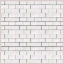
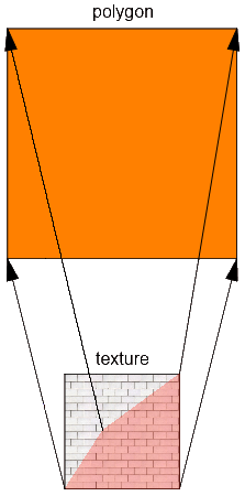
Texture mapping
Always check if texture mapping is applied correctly on your objects. If the default Archicad texture mapping process doesn’t produce a good result, use the coor{3} command to set the correct method.
When using different texture mapping modes, you should take care of correct axis definitions with vert, teve and coor{3} commands.
The node order is shown below.
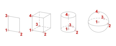
You can distort the textures by setting different distances between the nodes defined by the vert or teve commands.
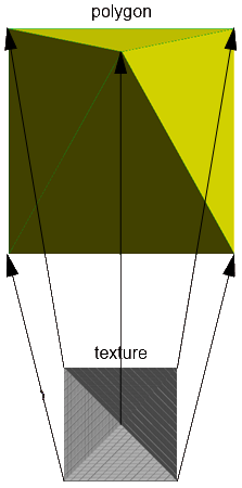
Take care that working with different rendering engines can produce slightly different results, see the examples.
Internal engine:
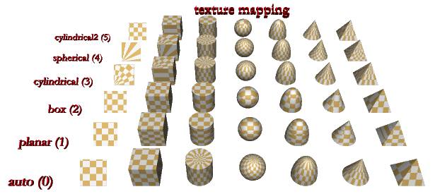
C4D engine:
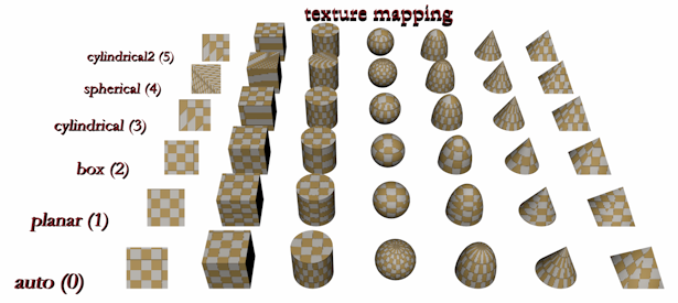
Correct texture mapping on complicated surfaces or distorted textures can be modeled with coor and teve commands. In this way you can make surface models only. In Archicad, there is no direct texture specification. You can define a texture as a part of a material definition. This texture is used in Rendering Engines and in OpenGL – but in OpenGL we have only limited implementation of our full texture mapping, and no texture (fill) mapping in our Internal 3D Engine at all.
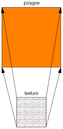
So with TEVE command you can map a planar texture point (u,v) to a spatial geometric point (x, y, z):
- (x, y, z) is measured in meters in the local coordinate system, as usual
- (u, v) is measured in units in the infinite texture space. One unit is as long as the texture extent in that direction.
You can give a negative or more than one value for either u or v.
See the example 1:
Table 12.4. Teve example 1: mapping with no distortion
| Program | Logic | Result |
|---|---|---|
base teve 0, 0, 1, 0, 0 teve 2, 0, 1, 1, 0 teve 0, 2, 1, 0, 1 teve 2, 2, 1, 1, 1 teve 0, 0, 1, 1, 1 edge 1, 2, -1, -1, 0 edge 2, 4, -1, -1, 0 edge 4, 3, -1, -1, 0 edge 3, 1, -1, -1, 0 set material 92 pgon 4, 0, 0, 1, 2, 3, 4 coor 1024, 1, 2, 3, -5 body -1 |
 |
 |
If you make a non-regular mapping, the Rendering engine will fit the shape in texture space to the shape in model space:
Table 12.5. Teve example 1: mapping with distortion
| Program | Logic | Result |
|---|---|---|
base teve 0, 0, 1, 0, 0 teve 2, 0, 1, 1, 0 teve 0, 2, 1, 0.3, 0.5 teve 2, 2, 1, 1, 1 teve 0, 0, 1, 1, 1 edge 1, 2, -1, -1, 0 edge 2, 4, -1, -1, 0 edge 4, 3, -1, -1, 0 edge 3, 1, -1, -1, 0 set material 92 pgon 4, 0, 0, 1, 2, 3, 4 coor 1024, 1, 2, 3, -5 body -1 |
 |
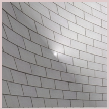 |
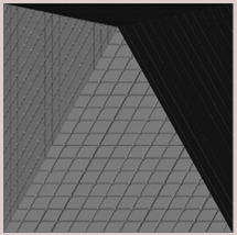
The same is true for real 3D bodies, as you can see in this example:
Table 12.6. Teve example 1: mapping with distortion on a pyramid
| Program | Logic | Result |
|---|---|---|
base teve 0, 0, 1, 0, 0 ! 1 teve 2, 0, 1, 2, 0 ! 2 teve 2, 2, 1, 2, 2 ! 3 teve 2, 2, 1, 0, 2 ! 4 teve 1, 1, 3, 1, 1 ! 5 edge 1, 2, -1, -1, 0 edge 2, 4, -1, -1, 0 edge 4, 3, -1, -1, 0 edge 3, 1, -1, -1, 0 set material 92 pgon 3, 0, 0, 1, 6, -5 coor 1024, -6, -7, -8, -9 body -1 |
 |
 |
Please note, that you can assign only one texture vertex for a model vertex. It is not possible to assign the texture vertices on a per polygon basis. It is sometimes an advantage and sometimes a disadvantage.
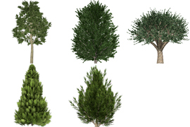
It may be a good idea to replace complicated parts of a model with a single picture. This method can be well used for trees and bushes.
Using an external image referred by its file name, don’t omit the file extension.
When you place a picture in a 3D model using the picture command, a polygon will be created using the picture as a face. The material of the polygon affects the result of the rendering. With this in mind you should use a matte surface – the color may be chosen depending on the picture.
define material "pictmat" 2,
        1, 1, 1             ! RGB

material "pictmat"

picture "filename.extension", a, b, mask
The first picture shows a picture on a shiny surface – the undesired side-effect can be observed. In the second picture you can see a texture on a precisely set material – the wanted result.
Table 12.7. Transparent images
| Shiny surface | Matte surface |
|---|---|
 |
 |
For transparent images – like the tree above – you should consider a more precise definition of the base material. See the following example.
define material "pictmat" 0,
        1, 1, 1,             ! RGB
        0.5, 0.8, 0, 0,
        0, 0,
        0, 0, 0,
        0, 0, 0,
        0

material "pictmat"

picture "filename", a, b, mask
Group operations
Group operations bring the power of solid operations into GDL. On the other hand they present a risk factor when misused.
An important point is that you mustn’t place a group inside another one. In such situations you should define a new group like in the source snippet below:
subtractionResult = subgroup ("sub_operand_1", "sub_operand_2")
Parameter script
Execution context
The parameter script is run in the following cases:
- Opening the Object Settings dialog window
- Changing a parameter’s value in the Object Settings dialog window
- Changing a parameter’s value using editable hotspots (even while generating the feedback)
- Stretching the object using conventional hotspots
- loading step-by-step migration libraries (starting from AC18)
The parameter script MAY be run on:
- Dragging the object, in case the object refers to
SYMB_POS_X/SYMB_POS_Y - Update Zones runs the parameter script of the affected zones if necessary
The parameter script is NOT run on:
- Rebuild
- Changing scale
- Changing story
Editing multiple selection may result unintended parameter values. GLOB_MODPAR_NAME is empty in the objects that are not directly edited. Even if the user changed the parameter specified in an if GLOB_MODPAR_NAME condition, the else branch will be evaluated, meaning it can be overwritten in the indirectly edited object. There is a similar issue with different VALUES ranges.
Note that the parameter script may be run multiple times on a single user interaction. The reason for this is that the parameter script can change the value of parameters and this requires the parameter script to be run again, and so on. Therefore it makes no sense to increase a parameter value by one in the parameter script since you may not be able to predict the cardinality of executions.
The run of the parameter script is linear, and not necessarily multiple. You can force the parameter script to start only once by checking the Run the parameter script only once option in the object’s Compatibility Options panel, if you are sure you don’t need it to run many times. This can make objects react faster, saving time and computing resources.

General recommendation
You can define relations between parameters using the GLOB_MODPAR_NAME value (containing the name of the last modified parameter). For example you can make a circle object for which both the radius and the diameter can be set (maybe one of them via the parameter list and the other via editable hotspots). Don’t use this possibility to define the valid range of parameters – use values command instead.
User Interface script
Execution context
The User Interface script is displayed in only one context: the user interface tab page in the Object Settings dialog window.
The script is run on the initialization of the dialog window and after each user interaction and parameter change.
General recommendation
If you want the Custom Settings page to appear in the topmost UI selector as default instead of the parameter list, push the Set as Default button (or add the “STBit_UIDefault” bit to the “StatBits” section of the XML). Otherwise the parameter list will be the starting tab. For Hierarchical pages, push the Hierarchical Pages button in the GDL Editor/UI window (or add the “STBit_UIUseHierarchicalPages” bit to the “StatBits” section of the XML).
When styling texts, note that extra small letters cannot get any style but plain. In addition, Outline and Shadow styles have no effect on Windows platform.
Note that Archicad tries to match the fonts used in dialogs with the operating systems. When scripting graphical user interfaces on Windows, leave more space around texts otherwise Mac users will see truncated texts.
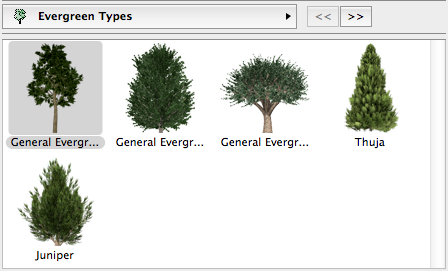
Thumbnail control pictures
If you use the ui_infield command to define a thumbnail view field for value lists, be aware of the following. There should be equal sized thumbnails for all parameter values (including empty value). Thumbnails have to be the same size at which they will be displayed otherwise Archicad will distort them. We advise you to use ‘s figure tool for assembling the thumbnails into one picture file.
Table 12.8. Infield with picture
| Input picture | Output picture |
|---|---|
 |
 |
A user interface picture used by only one object should be integrated in the library part file itself. This can be done using the LP_XMLConverter tool.
When using an external image referred to by its file name, don’t omit the file extension. This way, you will avoid errors stemming from pictures and objects having the same name.
Keep all pictures used by interface scripts in the Macros folder, or embedded in the object itself. Using external images: add the file_dependence command to make sure they are saved in archive format with the object.
Tab page handling
Starting from Archicad 18, a new hierarchical paging option is available for tabpage selection. This is accessed via the UI_PAGE command, by adding some extra parameters, and setting the Hierarchical Pages parameter in the object itself. Doing so, a separate popup tabpage control will appear above the custom UI field. The order and hierarchy of the available pages can be defined by the ID of the pages. Root ID is always -1. The possibility to set up an “oldschool” tabpage selector within the UI page still remains available.
Let’s see an example script:
! Master Script

! TabIDs
TABID_ROOT      = -1
TABID_PAGE_1    = 50
TABID_PAGE_2    = 60

dim uiUsedPageIDs[][2]
dim uiUsedPageNames[][2]
idxPage = 1

uiUsedPageNames[idxPage][1] = "PageName_1"
uiUsedPageNames[idxPage][2] = "pageIconName_1.png"

uiUsedPageIDs[idxPage][1]   = TABID_PAGE_1
uiUsedPageIDs[idxPage][2]   = TABID_ROOT    ! Parent Page ID

idxPage = idxPage + 1

uiUsedPageNames[idxPage][1] = "PageName_2"
uiUsedPageNames[idxPage][2] = "pageIconName_2.png"

uiUsedPageIDs[idxPage][1]   = TABID_PAGE_2
uiUsedPageIDs[idxPage][2]   = TABID_PAGE_1  ! Parent Page ID

file_dependence "pageIconName_1.png"
file_dependence "pageIconName_2.png"
file_dependence "pageIconName_3.png"
! Parameter Script

dim pageValues[]
for i = 1 to vardim1(uiUsedPageIDs)
    pageValues[i]= uiUsedPageIDs[i][1]
next i

values "gs_ui_current_page" pageValues
! UI Script

ui_dialog "Custom Settings Title"
ui_current_page gs_ui_current_page

for i = 1 to vardim1(uiUsedPageIDs)
    if uiUsedPageIDs[i][1] = TABID_PAGE_1 then
        ui_page uiUsedPageIDs[i][1],    uiUsedPageIDs[i][2],
                uiUsedPageNames[i][1],  uiUsedPageNames[i][2]
        if gs_ui_current_page = TABID_PAGE_1 then
            gosub "pageSubroutinTitle_1"
        endif
    endif

    if uiUsedPageIDs[i][1] = TABID_PAGE_2 then
        ui_page uiUsedPageIDs[i][1],    uiUsedPageIDs[i][2],
                uiUsedPageNames[i][1],  uiUsedPageNames[i][2]
        if gs_ui_current_page = TABID_PAGE_2 then
            gosub "pageSubroutinTitle_2"
        endif
    endif
next i

! ==============================================================================
! Call User Interface Macro's TabPages
! ==============================================================================

call "ui_customMacro" parameters all    uiUsedPageIDs   = uiUsedPageIDs,
                                        uiUsedPageNames = uiUsedPageNames

! ==============================================================================
end ! end ! end ! end ! end ! end ! end ! end ! end ! end ! end ! end ! end ! en
! ==============================================================================

! ==============================================================================
! UI Page Subroutines
! ==============================================================================

"pageSubroutinTitle_1":
    ! UI Page 1 description
return


"pageSubroutinTitle_2":
    ! UI Page 2 description
return
Thumbnail controls with dynamic items
From Archicad 10 on, a new dynamic method is available for linking control items and value list items. Using this method you can localize the logic of the availability of parameter values to the parameter script – the control will adopt the set of available values. This dynamic linking is available for ui_infield{3} and ui_infield{4}. The old-style static linking is still working for static functions (using ui_infield and ui_infield{2}).
The two components of the dynamic method are:
1. Define the user interface control with an option for every possible value.
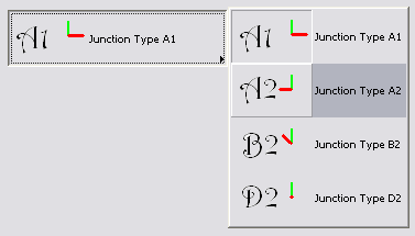
The example shows a popup menu control (method = 2) which uses an index image containing 2 rows and 4 columns. The sample control supports 8 possible values.
ui_infield{3} iJunctionType, xColumn1-10, 44, 200, 50,
    2, 3, 8, 2,
    70, 45, 70, 45,
    1, `Junction Type A1`, 2,
    2, `Junction Type B1`, 4,
    3, `Junction Type C1`, 1,
    4, `Junction Type D1`, 3,
    5, `Junction Type A2`, 5,
    6, `Junction Type B2`, 7,
    7, `Junction Type C2`, 6,
    8, `Junction Type D2`, 8
2. Set the list of available values for the parameter under the given circumstances.
if iLeftNeighbour = 1 then
    values "iJunctionType" 1, 3, 4, 6
else
    if iRightNeighbour = 1 then
        values "iJunctionType" 2, 5, 7, 8
    else
        values "iJunctionType" 1, 5, 7
    endif
endif
The resulting control is shown in the image below. (iLeftNeighbour = 0, iRightNeighbour = 1)
Transparent UI pictures
In Archicad 10 a new method has been introduced that can handle alpha-layer based transparent pictures. The following controls handle pictures with alpha layers correctly:
- ui_pict
- ui_infield{3}, method = 1 (thumbnail view control)
- ui_infield{3}, method = 2 (popup with icons and texts)
- ui_infield{3}, method = 3 (popup with icons only)
- ui_infield{3}, method = 4 (icon radio push button)
- ui_infield{4}, method = 1 (thumbnail view control)
- ui_infield{4}, method = 2 (popup with icons and texts)
- ui_infield{4}, method = 3 (popup with icons only)
- ui_infield{4}, method = 4 (icon radio push button)
Font sizes on the UI
If you use static texts (possibly in combination with the ui_style command), be aware of the following.
Because of the differences of the targeted operating systems, font sizes are not the same on Windows and on Mac. As a side effect, the extra small font size is a bit larger than the small one on Windows. As a general rule, always test user interfaces on both platforms to check overlapping and clipping.
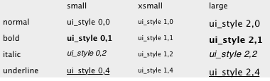
Furthermore, special styles like Bold, Italic and Underline are not allowed in combination with extra small size. Outline and Shadow are old Macintosh styles, which are no longer used.
The two pictures show the look of static texts with different sizes and styles.
On Windows:
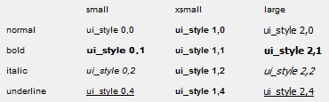
On Mac:
Forward Migration script
Execution context
The FWM script is executed when a project saved in an earlier version of Archicad is opened in a later version (starting with Archicad 15) with the updated library. This new library can be loaded manually or by using the Consolidate option in the Library Manager. If a placed instance of an object has a new, changed Main ID and a valid Forward Migration Script in the new library, it can be automatically substituted by Archicad. If the execution of the script is successful, the old element gets replaced by the new one. This script enables the object to set the new parameters based on the old ones, without feature loss or a major change in appearance.
General recommendation
The first line of the script fills the FROM_GUID global variable (this contains the main ID of the original object to be migrated) into the “actualGuid” variable. You may want to use the following structure to ensure maintainability.
The rest of the script is divided into subroutine calls, one for every change of GUID. Every block must have a corresponding line in the Migration Table of the object and a block in the Backward Migration script. The latest change of Main ID always has to be the last call of this script. In every block you set the ID to start from (_startID), and the one to end up with (_endID), define the migration logic in a subroutine (for details and GDL commands, see the GDL Reference Guide), and at the end of the block you always set the new “_endID” (or set an empty ID, which means that the upgrade process will stop at the previous block’s version of the object) into the “actualGuid” variable. Example:
actualGUID = FROM_GUID

! ==============================================================================
! Subroutines
! ==============================================================================

    _startID    = "AAAA-AAAA-...AAA"
    _endID      = "BBBB-BBBB-...BBB"
gosub "migrationstepname_FWM"

! ==============================================================================
! Set Migration GUID
! ==============================================================================

setmigrationguid actualGUID

! ==============================================================================
end ! end ! end ! end ! end ! end ! end ! end ! end ! end ! end ! end ! end ! en
! ==============================================================================


! ==============================================================================
! migrationstepname
! ==============================================================================
"migrationstepname_FWM":
    if actualGuid = _startID then
        newParameter = oldParameter
        parameters newParameter = newParameter
        actualGuid = _endID
    endif
return
Backward Migration script
Execution context
The BWM script is executed when a project is saved to the previous version of Archicad.
If the current version of the library part has a different Main ID than its equivalent in the previous version, the migration script of the object is evaluated. As a result, the libpart will be either downgraded if possible (sometimes with some minor compromise, if it does not affect the item’s main functions), or will be lost completely (in this case, it will appear as a “missing” dot sign in the earlier version project). The latter happens when a new function set introduced in the current version represents a major change compared to the previous version.
A successful backward migration process should convert the object’s parameters in a way that avoids major feature loss or changes in appearance.
General recommendation
The first line of the script sets the continuity control variable to valid. You may want to use the following structure to ensure maintainability.
The rest of the script is divided into subroutines: one change of Main ID is one subroutine. Every subroutine must have a corresponding line in the Migration Table of the object and a corresponding subroutine in the Forward Migration script. The latest step back in changing Main ID always has to be the first subroutine of this script.
At the start of each subroutine the target GUID is checked. If not empty, the script runs in called order. Backward migration only works for one version back, so the targetGUID only needs to be set once (except when you make a fork in the migration to separate previous-version objects).
The end of the subroutine is about setting the destination (old) ID into the “targetGuid” variable. If you set an empty ID to the variable, the downgrade process is canceled there. If the “targetGuid” matches the TO_GUID global variable (containing the main ID of the target element in the conversion), the first part of the migration process is complete.
Adding a title or a short description of the migration step for every subroutine is highly recommended. You should use the same title for the Forward Migration script pair of the subroutine.
After you have reached the desired stage of the object’s devolution, you have to set the placed object’s ID by using the setmigrationguid command.
In case the migration returns an empty ID, the element is going to be missing from the project opened in the previous version.
targetGUID = TO_GUID

! ==============================================================================
! Subroutines
! ==============================================================================

gosub "migrationstepname_BWM"

! ==============================================================================
! Set Migration GUID
! ==============================================================================

setmigrationguid targetGUID

! ==============================================================================
end ! end ! end ! end ! end ! end ! end ! end ! end ! end ! end ! end ! end ! en
! ==============================================================================


! ==============================================================================
! migrationstepname
! ==============================================================================
"migrationstepname _BWM":
    if targetGUID # "" then
        bMigrationSuccess = 1
        if bMigrationSuccess = 1 then
            oldParameter = newParameter
            parameters oldParameter = oldParameter
        else
            targetGuid = ""
        endif
    endif
return
Migration table
Every time you change an object’s Main ID, you need to fill in the old ID into the Migration Table of the element.
Each line contains a previous ID and an Archicad version number, or -1 for version independent migration (or 0, if you change more than once between two versions).
During forward migration, the program scans this list of ID-s, preselecting the elements available for the migration process.
During backward migration, scanning this list the program chooses only those with a version equivalent to the previous Archicad version.
If an item with version -1 is in the list, only that will be chosen, regardless of the previous AC version.
Every line of this table must have at least one corresponding subroutine in the Forward Migration script and the Backward Migration script.
Automigration can be used to run the parameter script without having to write a migration script that would only unconditionally change the GUID. It is useful if the migration code would have to be copied in the parameter script too for non-migrated elements (e.g. synchronizing parameters is needed as a bugfix or because new ac_ parameters).