With the growing demand for realistic rendering, the 3D models of your objects are getting more and more important. It is not easy to know where to stop in detailing: the purpose of the object may help sometimes, but the best way is to cover all areas: give your object a nearly full-detail model, and a more simple, abstract model as well.
Most objects around us consist of basic shapes, so after an evaluation of the forms, and finding out the kind of solid element operations you might need, nothing is impossible, nearly.
To create a 3D model for your object, use the Master script and the 3D script.
Make sure your 3D model covers the position of its 2D counterpart.
Transformations in model space
All transformation types are available in 3D. You can define a transformation in 3 directions at once, or using the axes, define a move along one of them:
add xOffset, yOffset, zOffset
addx xOffset
addy yOffset
addz zOffset

rotx alpha
roty alpha
rotz alpha

mul xProportion, yProportion, zProportion
mulx xProportion
muly yProportion
mulz zProportion
The transformation affects all elements placed after it in the script, until deleted (del).
See the GDL Manual – 3D Transformations chapter for more.
Attributes of a 3D model
When an attribute command is placed in the code, all subsequent elements will be displayed with the set attributes, unless the element declares its own (complex commands may include attribute definition parameters as well). If the script has no attribute definitions, general attributes will take action.
Surface (material)
One of the main features of a 3D model is its surface.
Every 3D shape without its own surface definition will be displayed with the surface of matching index according to template, after the attribute command.
material matIndex
The “matIndex” parameter is an integer, or the name of the surface between quotes. You can assign a surface type parameter from the object’s own parameters as well. This case, use the name of the surface type parameter instead of an index (without quotes).
Pen
Every 3D shape with edges following this command will be displayed with the pen of matching index according to template.
pen indexPen
The “indexPen” parameter is an integer. You can assign a pen type parameter from the object’s own parameters as well. This case, use the name of the pen type parameter instead of an index (without quotes).
Resolution
When dealing with segmented bodies, setting the right resolution can make the difference. The command resol sets smoothness for cylindrical elements and arcs in polylines. The default value is 36.
resol n
Circles are converted to regular polygons having n sides.
Shadow
Shadow can be enabled or disabled for your placed objects using the SHADOW command at the beginning of your script:
if gs_shadow then
	shadow ON
else
	shadow OFF
endif
…where “gs_shadow” is a boolean parameter of the object.
You can control the shadow casting ability of your scripted subparts individually, too. See the example in GDL Reference guide at the command definition.
Casting shadow for transparent objects correctly can be achieved by using the tips of Modeling transparent Bodies section.
Basic 3D shapes
There are many GDL commands to generate 3D shapes. Only some basic ones will be covered here.
For the full list, refer to Chapter 4. 3D Shapes of the GDL Manual.
Block
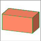
The body is defined by its 3 dimensions, oriented along the local coordinate system’s actual position.
block xDim, yDim, zDim
Sphere
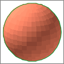
Only one parameter here: the radius of the sphere. It is always placed into the centerpoint of the local coordinate system.
sphere radius
Cylind
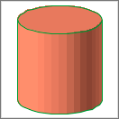
This command defines a cylind standing on the local x-y plane, stretching in the direction of the z-axis.
cylind height, radius
Cone
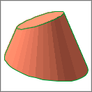
This command defines a cone standing on the local x-y plane, stretching in the direction of the z-axis. The angles of inclination of the end surfaces can be set in relations to the z axis.
cone height, radBottom, radTop, inclAngleBottom, inclAngleTop
General prism
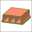
The prism body stands on the local x-y plane, stretching parallel to z-axis (height can be negative).
This function is a bit more complex than the previous ones: not only the geometric outline is declared, but the edge/side visibility, and some attributes of the base polygon itself can be customized using the various command forms available (differing only in parameter levels).
GDL’s prism is not a mathematical function: the base polygon’s edges can be arched or linear, and the polygon can contain holes as well (the base polygon part of the command is almost exactly the same as the planar polygon command’s).
For starters, let’s check out this parameter level (edges/sides can be omitted):
prism_ numControlPoints, height,
        x1, y1, s1,
        ...
        xn, yn, sn
- numControlPoints: the number of the defined points of the base polygon must be set here. A defined point is not necessarily the starting or endpoint of an edge, but it can be a centerpoint defined for an arched part of the contour line as well. Sometimes there is an extra point defined to close the polygon.
- height: the elevation of the prism
- x1 (xn), y1 (yn): coordinates of control points of the base polygon.
- s1 (sn): status bit of corresponding control points, a binary integer (between 0 and 127) or -1 (indicating the endpoint of an outer contour, or an inner hole definition).
The trio of xn, yn, sn usually defines a node of the base polygon. If the edge is a straight line, x and y are the coordinates of the endpoint of the edge on x-y plane, while s only controls the visibility of the edge and the attached plane: 1 (lower horizontal edge) + 2 (vertical edge) + 4 (upper horizontal edge) + 8 (side face).
When the edge is segmented, sn is not just a simple visibility bit for the edge or the side plane, but it defines the function of the xn, yn corresponding coordinates as well: they can be the centerpoint of an arch (s = 900), a tangent of an arch (s = 800), etc.
To see the whole collection of extra status point options, see the Status Codes section (Chapter 7.), or check out this tutorial’s section about Additional status codes.