Sometimes scripting a realistic 2D symbol for your object can be more than challenging. Using project commands is the easiest solution in these cases.
Let’s explore the functions of the most enhanced project command, PROJECT2{3} of ARCHICAD 19 through examples and explanations:
PROJECT2{3} projection_code, angle, method, parts [, backgroundColor,
        fillOrigoX, fillOrigoY, filldirection][[,]
        PARAMETERS name1=value1, ..., namen=valuen]
Example object can be downloaded here.
The default attributes are the following:

projection_code
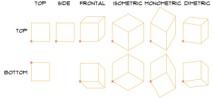
The options for the view direction are pretty straightforward: set the projection_code parameter as convenient by choosing from the provided value list (top, view, side view, side view 2 (same as side view, with an additional built-in transformation: mul2 -1, -1), frontal, isometric, monometric or dimetric anonometry, or any of the previous with bottom view except side option).
method
The command has 3 basic display methods, and 11 additional modifiers to affect the attributes of the displayed parts.
The basic methods are the following:
- wireframe: the model is projected as wireframe. No fill polygon is exported.
- hidden lines: the model is projected as wireframe, but certain lines are omitted. No fill polygon is exported.
- shading: the model is displayed with “colored” polygons. The color is generated from the 3D surface of the object set with MATERIAL command in the 3D script.
All 3 cases use the pen indexed in the PEN command. In case there is a PEN command in 3D, that takes preference over the pen set in the 2D script by default.
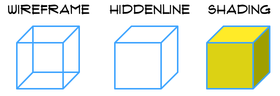
As for the additional modifier bits: not all combinations make sense, so think through which attributes should be modified by them, and which projected parts should the modified attributes affect.
Most usable combinations:
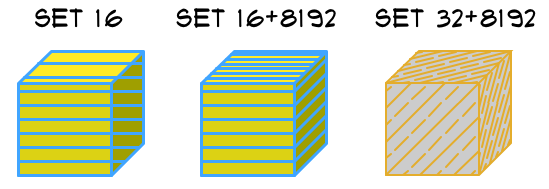
16+8192
- 16: set this bit to allow the vectorial hatch of the 3D surface to appear on the projection.
- 8192: if this is set with 16, the hatch of the distorted sides are oriented as well.
32+8192
- 32: set this bit to use the general attributes of the 2D script to override the vectorial hatch and attributes coming from the 3D script. The FILL command takes care of the filltype, the PEN command sets the foreground and contour pens of the projection, while the fill background pen is set in the
backgroundColorparameter of PROJECT2{3} command. - 8192: if this is set with 32, the hatch of the distorted sides are oriented as well.
The next level of combinations requires the cutting of the projected body in 3D (use the Cut in 3D parameter of the example object).
With a cut surface in the model, new options become available.
First, try them in wireframe mode:

Next, check the shading mode:
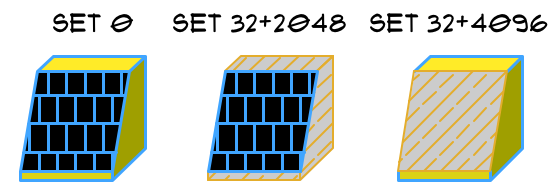
The “black” background pen is hardcoded by default if the cut surface has a vectorial hatch, and adding the flag 8192 can make it worse.
If the cut surface doesn’t have a vectorial hatch, it is displayed as a foreground fill with the current contour pen color.
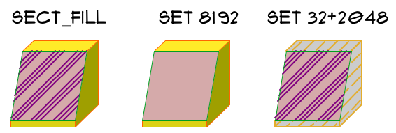
Fortunately, there is a way to fully control the displayed attributes of the cut surface: use the SECT_FILL command (or the SECT_ATTRS command) in the 3D script to set up a full attribute package for the projected cut area.
In the example object, we used the following parameters:

Note:
- using flag 32 overrides the SECT_FILL attributes with the current 2D attributes. Counteract it with setting flag 2048 as well.
- Setting the flag 8192 eliminates the SECT_FILL filltype, overwriting it with a background filltype.
A few tips for the rest of the additional modifier flags:
- 64: set this flag to use local fill orientation. The parameters can be set in the command’s
fillOrigoX, fillOrigoY, filldirectionoptional parameters. - 128 and 256: set property for the lines of the projections, similar to LINE_PROPERTY command. Works together with MVO/Override Fill Display/Override Cut Fills/Show Skin Separator Lines setting.
- 512 and 1024: use these to change the status of the default drafting fills of the projection. The Model View Options/Override Fill Display function uses these settings.
Wireframe mode, setting the inner line attribute for the view-parts, with the MVO Show Skin Separator OFF:
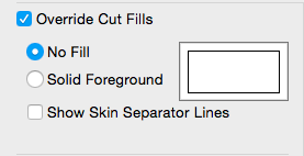
Result:
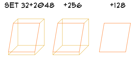
parts
This parameter allows to display optional parts of the whole projection by categories:
- control the visibility of cut polygons and lines
- control the visibility of view polygons and lines
- control the visibility of status parts (hotlines, hotspots, hotarcs)
parameters name = value
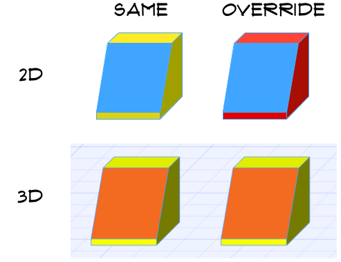
There is an option to control parameters of the 3D model and change them only for the 2D projection, so the 3D will stay intact.
In the example, the uncut surface gets and override value in the PROJECT command:
! override 3D Surface for projection only
if bProj3DOverride then
	_surfaceProjected = matProjected
else
	_surfaceProjected = matShape
endif

project2{3} iProjectionCode, angleProjection, _method, _parts,
		fillBGPenGeneral,
        _fillOrigoX, _fillOrigoY, _filldirection,
		parameters matShape = _surfaceProjected
