The MEP Add-On functions can be accessed through the MEP_m_ConnectionsACL_4 macro object.
This macro works as a link between the Add-On and the objects.
If you wish to create custom objects with MEP functions, save a copy of this macro with a different name, and use the copy in scripts.
Set subtype and add required parameters
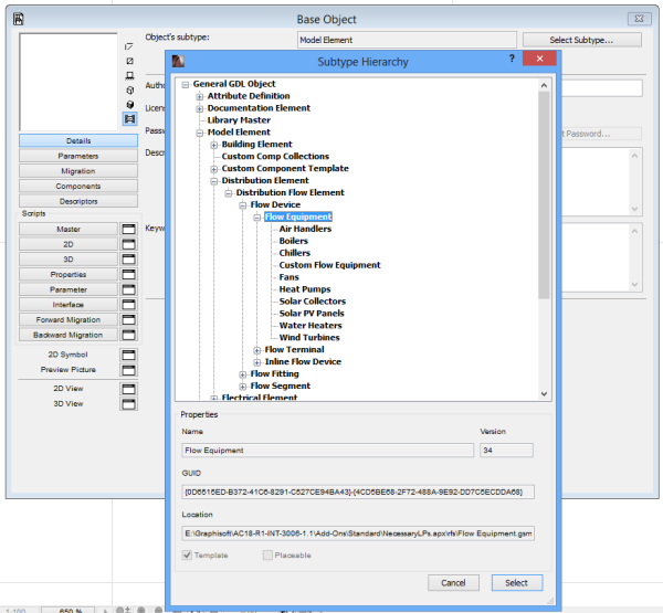
Open the library object you wish to extend with MEP in GDL editor and change its subtype to Flow Equipment.
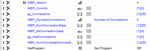
This subtype contains the parameters required by the MEP Add-on. The “SetProgram” parameter has to be added manually. This controls the direction of parameter value-flow between your object and the Add-On.
Add some more necessary parameters: the connections parameters. These parameters have to be added manually, and need to be set up individually for each connection your object is going to have. The maximum number of connections is 18.
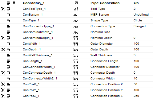
The parameter set in case of pipe connection:
The parameter set in case of duct connection:
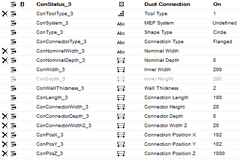
The Tool Type (“ConToolType_ID”) parameter sets the connection to Duct (1) or Pipe (2).
The MEP System (“ConSystem_ID”), Shape Type (“ConType_ID”) and Connection Type (“ConConnectorType_ID”) parameter values are set by the MEP Add-On.
Parameter script
First, the “MEP_NumberConnections” parameter has to be set. An equipment object can have 1 to 18 connections. The required scripts of a connection are the following:
- Validation of the shape type in the shape_typ_to_validation array. Pipe Connector can only have circle shape. Duct Connector can have all the available shapes (Rectangle, Circle, Oval).
dim shape_typ_to_validation[3] shape_typ_to_validation[1] = 0 ! Rectangle shape_typ_to_validation[2] = 1 ! Circle shape_typ_to_validation[3] = 0 ! Oval - Adding connection identification – (1 to 18)
ConID = 1
- Setting connection name
ConName = `Exhaust Connection`
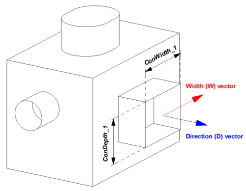
- Setting the direction and width vectors of the connection
! Direction (D) vector
 ConDVecX = 0
 ConDVecY = 1
 ConDVecZ = 0

 ! Width (W) vector
 ConWVecX = 1
 ConWVecY = 0
 ConWVecZ = 0
- Setting the connection size and its editing range, the connection position or the moving range
if not(SetProgram) then values "ConWidth_1" range (0, min(A, B)] ! Add editing range parameters ConDepth_1 = ConWidth_1 ! Linking of size parameters values "ConWallThickness_1" range [0, ConWidth_1] ! Add editing range values "ConPosX_1" range [ConWidth_1/2, A-ConWidth_1/2] ! Add moving range values "ConPosY_1" range [ConWidth_1/2, B-ConWidth_1/2] ! Add moving range parameters ConPosZ_1 = 0 ! Add fix position endif - Calling the “MEP_m_ConnectionsACL_4” macro and setting MEP_ConInfo array. The parameters with the ConID index (paramName_ID) should follow the ConID in the macro call.
call "MEP_m_ConnectionsACL_4" parameters SetProgram = SetProgram,
	gs_Connections			= gs_Connections,
	MEP_NumConnectionData		= MEP_NumConnectionData,
	MEP_StrConnectionData		= MEP_StrConnectionData,
	MEP_NumberConnections		= MEP_NumberConnections,
	gs_AddConnections		= gs_AddConnections,
	ConName				= ConName,
	ConID				= ConID,
	ConPosX				= ConPosX_1,
	ConPosY				= ConPosY_1,
	ConPosZ				= ConPosZ_1,
	ConDVecX			= ConDVecX,
	ConDVecY			= ConDVecY,
	ConDVecZ			= ConDVecZ,
	ConWVecX			= ConWVecX,
	ConWVecY			= ConWVecY,
	ConWVecZ			= ConWVecZ,

	ConNominalWidth			= ConNominalWidth_1,
	ConNominalDepth			= ConNominalDepth_1,
	ConWidth			= ConWidth_1,
	ConDepth			= ConDepth_1,
	ConLength			= ConLength_1,
	ConWallThickness		= ConWallThickness_1,
	ConConnectorWidth		= ConConnectorWidth_1,
	ConConnectorDepth		= ConConnectorDepth_1,
	ConConnectorWidth2		= ConConnectorWidth2_1,
	ConToolType			= ConToolType_1,
	ConStatus			= ConStatus_1,
	ConType_1			= ConType_1,
	ConConnectorType_1		= ConConnectorType_1,
	ConSystem_1			= ConSystem_1,
	shape_typ_to_validation		= shape_typ_to_validation,
	MEP_enabled_geometry_mod	= 1,
	gs_ui				= 0

parameters MEP_ConInfo[ConID][1] = str(ConToolType_1, 1, 0)
parameters MEP_ConInfo[ConID][2] = ConName
parameters MEP_ConInfo[ConID][3] = "0"
- After all of the connection macro calls the SetProgram parameter has to be reset. This parameter is set to ‘ON’ by the MEP Add-On to control the connection data flow direction. Set if to ‘OFF’ to allow the library part to control the data.
if SetProgram then
	SetProgram = 0
	parameters SetProgram = SetProgram
endif
2D Representation
In 2D Script one macro call takes care of all connections:
call "MEP_m_ConnectionsACL_4" parameters SetProgram = SetProgram,
	MEP_NumberConnections	= MEP_NumberConnections,
	MEP_NumConnectionData	= gs_Connections,
	gs_AddConnections	= gs_AddConnections,
	DrawingNum		= 1,
	MEP_InsShow		= 0,
	MEP_cline_show		= 0,
	gs_cont_pen		= gs_cont_pen,
	gs_fill_type		= gs_fill_type,
	gs_fill_pen		= gs_fill_pen,
	gs_back_pen		= gs_back_pen,
	ConPosX_1		= ConPosX_1,
	ConPosY_1		= ConPosY_1,
	ConLength_1		= ConLength_1,
	ConShow_1		= 1,
	ConEdit_1 		= 12,
	. . .
The macro call contains the settings of connection editing types (ConEdit_[ConID]).
- 0: no editing
- 1: connection length editing
- 2: connection position editing along X axis of local coordinate system
- 3: connection position editing along Y axis of local coordinate system
- 4: connection position editing along Z axis of local coordinate system
- 5: connection position editing along X and Y axis of local coordinate system
- 6: connection position editing along X and Z axis of local coordinate system
- 7: connection position editing along Y and Z axis of local coordinate system
- 12: connection length and position editing along X axis of local coordinate system
- 13: connection length and position editing along Y axis of local coordinate system
- 14: connection length and position editing along Z axis of local coordinate system
- 15: connection length and position editing along X and Y axis of local coordinate system
- 16: connection length and position editing along X and Z axis of local coordinate system
- 17: connection length and position editing along Y and Z axis of local coordinate system
3D Representation
In 3D Script one macro call handles all of the connections as well:
call "MEP_m_ConnectionsACL_4" parameters SetProgram = SetProgram,
	MEP_NumberConnections	= MEP_NumberConnections,
	MEP_NumConnectionData	= gs_Connections,
	gs_AddConnections	= gs_AddConnections,
	cShow3D			= 1,
	gs_ConMat		= gs_mat,
	MEP_InsShow		= 0,
	MEP_cline_show_3D	= 0,
	gs_cont_pen		= gs_cont_pen,
	ConPosX_1		= ConPosX_1,
	ConPosY_1		= ConPosY_1,
	ConPosZ_1		= ConPosZ_1,
	ConLength_1		= ConLength_1,
	ConEdit_1 		= 16,
	. . .
The macro call contains the settings of connection editing types (ConEdit_[ConID]). See the 2D representation stage for its possible values.
Command and function pool:
DIM
VALUES
PARAMETERS
CALL
STR
