BLOCK
BLOCK a, b, c
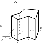
BRICK
BRICK a, b, c
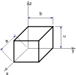
The first corner of the block is in the local origin and the edges with lengths a, b and c are along the x-, y- and z-axes, respectively.
Zero values create degenerated blocks (rectangle or line).
a >= 0, b >= 0, c >= 0
a + b + c > 0
CYLIND
CYLIND h, r
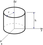
Right cylinder, coaxial with the z-axis with a height of h and a radius of r.
If h=0, a circle is generated in the x-y plane.
If r=0, a line is generated along the z axis.
SPHERE
SPHERE r
A sphere with its center at the origin and with a radius of r.

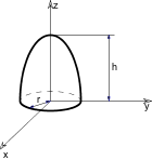
ELLIPS
ELLIPS h, r
Half ellipsoid. Its cross-section in the x-y plane is a circle with a radius of r centered at the origin.
The length of the half axis along the z-axis is h.
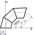
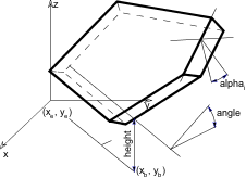
CONE
CONE h, r1, r2, alpha1, alpha2

Frustum of a cone where alpha1 and alpha2 are the angles of inclination of the end surfaces to the z axis,
r1 and r2 are the radii of the end-circles and h is the height along the z axis.
If h=0, the values of alpha1 and alpha2 are disregarded and an annulus is generated in the x-y plane.
alpha1 and alpha2 are in degrees.
0 < alpha1 < 180° and 0 < alpha2 < 180°
PRISM
PRISM n, h, x1, y1, ..., xn, yn
Right prism with its base polygon in the x-y plane
(see the parameters of the POLY command and the POLY_ command).
The height along the z-axis is abs(h). Negative h values can also be used. In that case the second base polygon is below the x-y plane.
n >= 3
PRISM_
PRISM_ n, h, x1, y1, s1, ..., xn, yn, sn
Similar to the PRISM command, but any of the horizontal edges and sides can be omitted.
n >= 3
si: status code that allows you to control the visibility of polygon edges and side surfaces.
You can also define holes and create segments and arcs in the polyline using special constraints.
See Chapter 7, Status Codes for details.
Example 1:
Solid and hollow faces
 |
 |
PRISM_ 4,1,
    0,0,15,
    1,1,15,
    2,0,15,
    1,3,15
|
PRISM_ 4,1,
    0,0,7,
    1,1,5,
    2,0,15,
    1,3,15
|
Example 2:
Holes in the polygon

ROTX 90
PRISM_ 26, 1.2,
    0.3,   0,    15,
    0.3,   0.06, 15,
    0.27,  0.06, 15,
    0.27,  0.21, 15,
    0.25,  0.23, 15,
    -0.25, 0.23, 15,
    -0.27, 0.21, 15,
    -0.27, 0.06, 15,
    -0.3,  0.06, 15,
    -0.3,  0,    15,
    0.3,   0,    -1,    !End of contour
    0.10,  0.03, 15,
    0.24,  0.03, 15,
    0.24,  0.2,  15,
    0.10,  0.2,  15,
    0.10,  0.03, -1,    !End of first hole
    0.07,  0.03, 15,
    0.07,  0.2,  15,
    -0.07, 0.2,  15,
    -0.07, 0.03, 15,
    0.07,  0.03, -1,    !End of second hole
    -0.24, 0.03, 15,
    -0.24, 0.2,  15,
    -0.1,  0.2,  15,
    -0.1,  0.03, 15,
    -0.24, 0.03, -1     !End of third hole
|
Example 3:
Curved surface
 |
|
j7 = 0 |
j7 = 1 |
R = 1
H = 3
PRISM_ 9, H,
        -R,         R,          15,
        COS(180)*R, SIN(180)*R, 15,
        COS(210)*R, SIN(210)*R, 15,
        COS(240)*R, SIN(240)*R, 15,
        COS(270)*R, SIN(270)*R, 15,
        COS(300)*R, SIN(300)*R, 15,
        COS(330)*R, SIN(330)*R, 15,
        COS(360)*R, SIN(360)*R, 15,
        R,          R,          15
|
R = 1
H = 3
PRISM_ 9, H,
        -R,         R,          15,
        COS(180)*R, SIN(180)*R, 64+15,
        COS(210)*R, SIN(210)*R, 64+15,
        COS(240)*R, SIN(240)*R, 64+15,
        COS(270)*R, SIN(270)*R, 64+15,
        COS(300)*R, SIN(300)*R, 64+15,
        COS(330)*R, SIN(330)*R, 64+15,
        COS(360)*R, SIN(360)*R, 64+15,
        R,          R,          15
|
CPRISM_
CPRISM_ top_material, bottom_material, side_material,
        n, h,
        x1, y1, s1, ..., xn, yn, sn
Extension of the PRISM_ command. The first three parameters are used for the material name/index of the top, bottom and side surfaces.
The other parameters are the same as above in the PRISM_ command.
n >= 3
See also the section called “Materials”.
si: status code that allows you to control the visibility of polygon edges and side surfaces.
You can also define holes and create segments and arcs in the polyline using special constraints.
See Chapter 7, Status Codes for details.
Example:
Material referencing a predefined material by name, index and global variable

CPRISM_ "Mtl-Iron", 0, SYMB_MAT,
        13, 0.2,
        0, 0, 15,
        2, 0, 15,
        2, 2, 15,
        0, 2, 15,
        0, 0, -1,            !end of the contour
        0.2, 0.2, 15,
        1.8, 0.2, 15,
        1.0, 0.9, 15,
        0.2, 0.2, -1,        !end of first hole
        0.2, 1.8, 15,
        1.8, 1.8, 15,
        1.0, 1.1, 15,
        0.2, 1.8, -1         !end of second hole
CPRISM_{2}
CPRISM_{2} top_material, bottom_material, side_material,
        n, h,
        x1, y1, alpha1, s1, mat1,
        ...
        xn, yn, alphan, sn, matn
CPRISM_{2} is an extension of the CPRISM_ command with the possibility of defining different angles and materials for each side of the prism.
The side angle definition is similar to the one of the CROOF_ command.
alphai: the angle between the face belonging to the edge i of the prism and the plane perpendicular to the base.mati: material reference that allows you to control the material of the side surfaces.CPRISM_{3}
CPRISM_{3} top_material, bottom_material, side_material, mask,
          n, h,
          x1, y1, alpha1, s1, mat1,
          ...
          xn, yn, alphan, sn, matn
CPRISM_{3} is an extension of the CPRISM_{2} command with the possibility of controlling the global behavior of the generated prism.
mask: controls the global behavior of the generated prism.mask = j1 + 2*j2 + 4*j3 + 8*j4, where each j can be 0 or 1.j1: top edge in line elimination.j2: bottom edge in line elimination.j3: side edge in line elimination.j4: side edge and surface is smooth in curved sections of the profile.Compatibility: introduced in ARCHICAD 21.
Example:
PEN 1
mat = IND (MATERIAL, "Metal-Aluminium")
FOR i=1 TO 4 STEP 1
  IF i = 1 THEN mask = 1+2+4
  IF i = 2 THEN mask = 1
  IF i = 3 THEN mask = 2
  IF i = 4 THEN mask = 4
  CPRISM_{3} mat, mat, mat, mask,
      5, 1,
      0, 0, 0, 15, mat,
      1, 0, 0, 15, mat,
      1, 1, 0, 15, mat,
      0, 1, 0, 15, mat,
      0, 0, 0, -1, mat
  BODY -1
  DEL TOP
  IF i = 1 THEN ADDY 1
  IF i = 2 THEN ADDX -1
  IF i = 3 THEN ADDX 1
NEXT i
|

Example:
PEN 1
mat = IND (MATERIAL, "Metal-Aluminium")
!visible side segment edges
mask = 1 + 2 + 4
_secondStat = 15
CPRISM_{3} mat, mat, mat, mask,
	6,	1,
	0,	0,   0, 15,		mat,
	1,	0,   0, _secondStat,	mat,
	0.5, 	0.5, 0, 900,		mat,
	1,	1,   0, 3015,		mat,
	0,	1,   0, 15,		mat,
	0,	0,   0, -1,		mat
|
 |
!smooth edges using first node status copy
mask = 1 + 2 + 4
_secondStat = 15 + 64
CPRISM_{3} mat, mat, mat, mask,
	6,   1,
	0,   0,   0, 15,		mat,
	1,   0,   0, _secondStat,	mat,
	0.5, 0.5, 0, 900,		mat,
	1,   1,   0, 3015,		mat,
	0,   1,   0, 15,		mat,
	0,   0,   0, -1,		mat
|
 |
!smooth edges using mask, first edge is not smooth
mask = 1 + 2 + 4 + 8
_secondStat = 15
CPRISM_{3} mat, mat, mat, mask,
	6,   1,
	0,   0,   0, 15,		mat,
	1,   0,   0, _secondStat,	mat,
	0.5, 0.5, 0, 900,		mat,
	1,   1,   0, 3015,		mat,
	0,   1,   0, 15,		mat,
	0,   0,   0, -1,		mat
|
 |
CPRISM_{4}
CPRISM_{4} top_material, bottom_material, side_material, mask,
          n, h,
          x1, y1, alpha1, s1, mat1,
          ...
          xn, yn, alphan, sn, matn
CPRISM_{4} is an extension of the CPRISM_{3} command
with the possibility of using inline material definition, that means materials defined in GDL script locally
also can be used next to materials defined in global material definitions.
BPRISM_
BPRISM_ top_material, bottom_material, side_material,
        n, h, radius,
        x1, y1, s1,
        ...
        xn, yn, sn
A smooth curved prism, based on the same data structure as the straight CPRISM_ element. The only additional parameter is radius.
Derived from the corresponding CPRISM_ by bending the x-y plane onto a cylinder tangential to that plane. The cylinder is on the bottom side of the x-y plane.
Prism with positive thickness will be constructed outside the cylinder; prism with negative thickness will be constructed inside the cylinder.
Edges along the x axis are transformed to circular arcs; edges along the y axis remain horizontal;
edges along the z axis will be radial in direction.
See the BWALL_ command for details.
si: status code that allows you to control the visibility of polygon edges and side surfaces.
You can also define holes and create segments and arcs in the polyline using special constraints.
See Chapter 7, Status Codes for details.
radius > 0
radius + height > 0
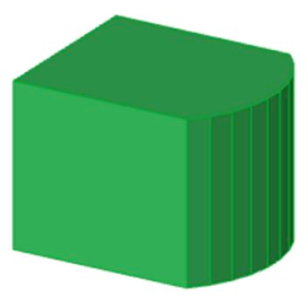
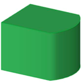
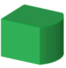
Example:
Curved prisms with the corresponding straight ones
BPRISM_ "Glass - Blue", "Glass - Blue", "Glass - Blue",
        3,   0.4, 1,        ! radius = 1
        0,   0,   15,
        5,   0,   15,
        1.3, 2,   15
|

BPRISM_ "Concrete", "Concrete", "Concrete",
        17,   0.3,  5,
        0,    7.35, 15,
        0,    2,    15,
        1.95, 0,    15,
        8,    0,    15,
        6.3,  2,    15,
        2,    2,    15,
        4.25, 4,    15,
        8,    4,    15,
        8,    10,   15,
        2.7,  10,   15,
        0,    7.35, -1,
        4,    8.5,  15,
        1.85, 7.05, 15,
        3.95, 5.6,  15,
        6.95, 5.6,  15,
        6.95, 8.5,  15,
        4,    8.5,  -1
|


FPRISM_
FPRISM_ top_material, bottom_material, side_material, hill_material,
        n, thickness, angle, hill_height,
        x1, y1, s1,
        ...
        xn, yn, sn
Similar to the PRISM_ command, with the additional hill_material, angle and hill_height parameters
for forming a ramp on the top.
hill_material: the side material of the ramp part.angle: the inclination angle of the ramp side edges.Restriction: 0 <= angle < 90.
If angle = 0, the hill side edges seen from an orthogonal view form a quarter circle with the current resolution
(see the RADIUS command, the RESOL command and the TOLER command).
hill_height: the height of the ramp. Note that the thickness parameter represents the whole height of the prism.si: status code that allows you to control the visibility of polygon edges and side surfaces.
You can also define holes and create segments and arcs in the polyline using special constraints.
n >= 3, hill_height < thickness
See Chapter 7, Status Codes for details.

Example 1:
Prism with curved ramp

RESOL 10
FPRISM_ "Roof Tile", "Brick-Red", "Brick-White", "Roof Tile",
        4, 1.5, 0, 1.0,        !angle = 0
        0, 0, 15,
        5, 0, 15,
        5, 4, 15,
        0, 4, 15
Example 2:
Prism with straight ramp

FPRISM_ "Roof Tile", "Brick-Red", "Brick-White",
        "Roof Tile",
        10, 2, 45, 1,
        0, 0, 15,
        6, 0, 15,
        6, 5, 15,
        0, 5, 15,
        0, 0, -1,
        1, 2, 15,
        4, 2, 15,
        4, 4, 15,
        1, 4, 15,
        1, 2, -1
HPRISM_
HPRISM_ top_mat, bottom_mat, side_mat,
        hill_mat,
        n, thickness, angle, hill_height, status,
        x1, y1, s1,
        ...
        xn, yn, sn
Similar to FPRISM_, with an additional parameter controlling the visibility of the hill edges.
status: controls the visibility of the hill edges:0: hill edges are all visible (FPRISM_)1: hill edges are invisibleSPRISM_
SPRISM_ top_material, bottom_material, side_material,
        n, xb, yb, xe, ye, h, angle,
        x1, y1, s1,
        ...
        xn, yn, sn
Extension of the CPRISM_ command, with the possibility of setting the upper polygon non-parallel with the x-y plane.
The upper plane definition is similar to the plane definition of the CROOF_ command.
The height of the prism is defined at the reference line.
Upper and lower polygon intersection is forbidden.

xb, yb, xe, ye: reference line (vector) starting and end coordinates.angle: rotation angle of the upper polygon around the given oriented reference line in degrees (CCW).si: status code that allows you to control the visibility of polygon edges and side surfaces.
You can also define holes and create segments and arcs in the polyline using special constraints.
See Chapter 7, Status Codes for details.
Note
All calculated z coordinates of the upper polygon nodes must be positive or 0.
Example:
SPRISM_ 'Grass', 'Earth', 'Earth',
        6,
        0, 0, 11, 6, 2, -10.0,
        0,   0,   15,
        10,  1,   15,
        11,  6,   15,
        5,   7,   15,
        4.5, 5.5, 15,
        1,   6, 15
|

SPRISM_{2}
SPRISM_{2} top_material, bottom_material, side_material,
        n,
        xtb, ytb, xte, yte, topz, tangle,
        xbb, ybb, xbe, ybe, bottomz, bangle,
        x1, y1, s1, mat1,
        ...
        xn, yn, sn, matn
Extension of the SPRISM_ command, with the possibility of having an upper and lower polygon non-parallel with the x-y plane.
The definition of the planes is similar to the plane definition of the CROOF_ command.
The top and bottom of the prism is defined at the reference line. Upper and lower polygon intersection is forbidden.
xtb, ytb, xte, yte: reference line (vector) of the top polygon starting and end coordinates.topz: the ‘z’ level of the reference line of the top polygon.tangle: rotation angle of the top polygon around the given oriented reference line in degrees (CCW).xbb, ybb, xbe, ybe: reference line (vector) of the bottom polygon starting and end coordinates.bottomz: the ‘z’ level of the reference line of the bottom polygon.bangle: rotation angle of the bottom polygon around the given oriented reference line in degrees (CCW).si: status code that allows you to control the visibility of polygon edges and side surfaces.
You can also define holes and create segments and arcs in the polyline using special constraints.
See Chapter 7, Status Codes for details.
mati: material reference that allows you to control the material of the side surfaces.Example:
SPRISM_{2} 'Grass', 'Earth', 'Earth',
        11,
        0, 0, 11, 0, 30, -30.0,
        0, 0, 0, 11, 2, 30.0,
        0,  0, 15, IND (MATERIAL, 'C10'),
        10, 1, 15, IND (MATERIAL, 'C11'),
        11, 6, 15, IND (MATERIAL, 'C12'),
        5,  7, 15, IND (MATERIAL, 'C13'),
        4,  5, 15, IND (MATERIAL, 'C14'),
        1,  6, 15, IND (MATERIAL, 'C10'),
        0,  0, -1, IND (MATERIAL, 'C15'),
        9,  2, 15, IND (MATERIAL, 'C15'),
        10, 5, 15, IND (MATERIAL, 'C15'),
        6,  4, 15, IND (MATERIAL, 'C15'),
        9,  2, -1, IND (MATERIAL, 'C15')
|

SPRISM_{3}
SPRISM_{3} top_material, bottom_material, side_material, mask,
        n,
        xtb, ytb, xte, yte, topz, tangle,
        xbb, ybb, xbe, ybe, bottomz, bangle,
        x1, y1, s1, mat1,
        ...
        xn, yn, sn, matn
Extension of the SPRISM_{2} command with the possibility of controlling the global behavior of the generated prism.
mask: controls the global behavior of the generated prism.mask = j1 + 2*j2 + 4*j3, where each j can be 0 or 1.j1: top edge in line elimination.j2: bottom edge in line elimination.j3: side edge in line elimination.j4: side edge and surface is smooth in curved sections of the profile.Compatibility: introduced in ARCHICAD 21.
Example:
PEN 1
mat = IND (MATERIAL, "Metal-Aluminium")
FOR i=1 TO 4 STEP 1
  IF i = 1 THEN mask = 1+2+4
  IF i = 2 THEN mask = 1
  IF i = 3 THEN mask = 2
  IF i = 4 THEN mask = 4
  SPRISM_{3} mat, mat, mat, mask,
      5,
      0,	0,	1,	0,	1,	0,
      0,	0,  1,  0,	0,	0,
      0,	0,	15, mat,
      1,	0,	15, mat,
      1,	1,	15, mat,
      0,	1,	15, mat,
      0,	0,	-1, mat

  BODY -1
  DEL TOP
  IF i = 1 THEN ADDY 1
  IF i = 2 THEN ADDX -1
  IF i = 3 THEN ADDX 1
NEXT i
|
SPRISM_{4}
SPRISM_{4} top_material, bottom_material, side_material, mask,
        n,
        xtb, ytb, xte, yte, topz, tangle,
        xbb, ybb, xbe, ybe, bottomz, bangle,
        x1, y1, s1, mat1,
        ...
        xn, yn, sn, matn
SPRISM_{4} is an extension of the SPRISM_{3} command
with the possibility of using inline material definition, that means materials defined in GDL script locally
also can be used next to materials defined in global material definitions.
SLAB
SLAB n, h, x1, y1, z1, ..., xn, yn, zn
Oblique prism. The lateral faces are always perpendicular to the x-y plane.
Its bases are flat polygons rotated about an axis parallel with the x-y plane.
Negative h values can also be used. In that case the second base polygon is below the given one.
No check is made as to whether the points are really on a plane. Apices not lying on a plane will result in strange shadings/ renderings.
n >= 3

SLAB_
SLAB_ n, h, x1, y1, z1, s1, ..., xn, yn, zn, sn
Similar to the SLAB command, but any of the edges and faces of the side polygons can be omitted.
This statement is an analogy of the PRISM_ command.
si: status code that allows you to control the visibility of polygon edges and side surfaces.
You can also define holes and create segments and arcs in the polyline using special constraints.
See Chapter 7, Status Codes for details.
CSLAB_
CSLAB_ top_material, bottom_material, side_material,
        n, h,
        x1, y1, z1, s1, ..., xn, yn, zn, sn
Extension of the SLAB_ command; the first three parameters are used for the material name/index of the top, bottom and side surfaces.
The other parameters are the same as above in the SLAB_ command.
si: status code that allows you to control the visibility of polygon edges and side surfaces.
You can also define holes and create segments and arcs in the polyline using special constraints.
See Chapter 7, Status Codes for details.
CWALL_
CWALL_ left_material, right_material, side_material,
        height, x1, x2, x3, x4, t,
        mask1, mask2, mask3, mask4,
        n,
        x_start1, y_low1, x_end1, y_high1, frame_shown1,
        ...
        x_startn, y_lown, x_endn, y_highn, frame_shownn,
        m,
        a1, b1, c1, d1,
        ...
        am, bm, cm, dm
Left_material, right_material, side_material: Material names/indices for the left, right and side surfaces. (The left and right sides of the wall follow the x axis.)
The reference line of the wall is always transformed to coincide with the x axis. The sides of the wall are in the x-z plane.
height: The height of the wall relative to its base.x1, x2, x3, x4: The projected endpoints of the wall lying on the x-y plane as seen below.
If the wall stands on its own, then x1 = x4 = 0, x2 = x3 = the length of the wall.
t: the thickness of the wall.t < 0: if the body of the wall is to the right of the x axis,t > 0: if the body of the wall is to the left of the x axis,t = 0: if the wall is represented by a polygon and frames are generated around the holes.
mask1, mask2, mask3, mask4: Control the visibility of edges and side polygons.
mask1, mask2, mask3, mask4 = j1 + 2*j2 + 4*j3 + 8*j4, where each j can be 0 or 1.The j1, j2, j3 bits represent whether the edges of the side polygon are present (1) or omitted (0). The j4 bit represents whether edges on the side polygon arisen from cut are present (1) or omitted (0).

n: the number of openings in the wall.x_starti, y_lowi, x_endi, y_highi: coordinates of the openings as shown below.
frame_showni: 1: if the edges of the hole are visible,0: if the edges of the hole are invisible,< 0: control the visibility of each of the opening’s edges separately: frame_showni = -(1*j1 + 2*j2 + 4*j3 + 8*j4 + 16*j5 + 32*j6 + 64*j7 + 128*j8), where j1, j2, …, j8 can be either 0 or 1.
The numbers j1 to j4 control the visibility of the edges of the hole on the left-hand side of the wall surface,
while j5 to j8 affect the edges on the right-hand side, as shown on the illustration below.

An edge that is perpendicular to the surface of the wall is visible if there are visible edges drawn from both of its endpoints.
m: the number of cutting planes.ai, bi, ci, di: coefficients of the equation defining the cutting plane [ai*x + bi*y + ci*z = di].
Parts on the positive side of the cutting plane (i.e., ai*x + bi*y + ci*z > di) will be cut and removed

BWALL_
BWALL_ left_material, right_material, side_material,
        height, x1, x2, x3, x4, t, radius,
        mask1, mask2, mask3, mask4,
        n,
        x_start1, y_low1, x_end1, y_high1, frame_shown1,
        ...
        x_startn, y_lown, x_endn, y_highn, frame_shownn,
        m,
        a1, b1, c1, d1,
        ...
        am, bm, cm, dm
A smooth curved wall based on the same data structure as the straight wall CWALL_ element. The only additional parameter is radius.
Derived from the corresponding CWALL_ by bending the x-z plane onto a cylinder tangential to that plane.
Edges along the x axis are transformed to circular arcs, edges along the y axis will be radial in direction, and vertical edges remain vertical.
The curvature is approximated by a number of segments set by the current resolution
(see the RADIUS command, the RESOL command and the TOLER command).
See also the CWALL_ command for details.


Example 2:
ROTZ -60
BWALL_ 1, 1, 1,
        4, 0, 6, 6, 0,
        0.3, 2,
        15, 15, 15, 15,
        5,
        1, 1, 3.8, 2.5, -255,
        1.8, 0, 3, 2.5, -255,
        4.1, 1, 4.5, 1.4, -255,
        4.1, 1.55, 4.5, 1.95,-255,
        4.1, 2.1, 4.5, 2.5, -255,
        1, 0, -0.25, 1, 3
|

XWALL_
XWALL_ left_material, right_material, vertical_material, horizontal_material,
        height, x1, x2, x3, x4,
        y1, y2, y3, y4,
        t, radius,
        log_height, log_offset,
        mask1, mask2, mask3, mask4,
        n,
        x_start1, y_low1, x_end1, y_high1,
        frame_shown1,
        ...
        x_startn, y_lown, x_endn, y_highn,
        frame_shownn,
        m,
        a1, b1, c1, d1,
        ...
        am, bm, cm, dm,
        status
Extended wall definition based on the same data structure as the BWALL_ element.
vertical_material, horizontal_material: name or index of the vertical/horizontal side materials.y1, y2, y3, y4: the projected endpoints of the wall lying in the x-y plane as seen below.
log_height, log_offset: additional parameters allowing you to compose a wall from logs. Effective only for straight walls.
status: controls the behavior of log wallsstatus = j1 + 2*j2 + 4*j3 + 32*j6 + 64*j7 + 128*j8 + 256*j9, where each j can be 0 or 1.j1: apply right side material on horizontal edges,j2: apply left side material on horizontal edges,j3: start with half log,j6: align texture to wall edges,j7: double radius on bended side,j8: square log on the right side,j9: square log on the left side.
Example:

XWALL_ "Surf-White", "Surf-White", "Surf-White", "Surf-White",
        3.0,
        0.0, 4.0, 4.0, 0.0,
        0.0, 0.0, 0.3, 1.2,
        1.2, 0.0,
        0.0, 0.0,
        15, 15, 15, 15,
        3,
        0.25, 0.0, 1.25, 2.5, -255,
        1.25, 1.5, 2.25, 2.5, -255,
        2.25, 0.5, 3.25, 2.5, -255, 0
XWALL_{2}
XWALL_{2} left_material, right_material, vertical_material, horizontal_material,
          height, x1, x2, x3, x4,
          y1, y2, y3, y4,
          t, radius,
          log_height, log_offset,
          mask1, mask2, mask3, mask4,
          n,
          x_start1, y_low1, x_end1, y_high1,
          sill_depth1, frame_shown1,
          ...
          x_startn, y_lown, x_endn, y_highn,
          sill_depthn, frame_shownn,
          m,
          a1, b1, c1, d1,
          ...
          am, bm, cm, dm,
          status
Extended wall definition based on the same data structure as the XWALL_ element.
silldepthi: logical depth of the opening sill. If the j9 bit of the frame_showni parameter is set,
the wall side materials wraps the hole polygons, silldepthi defining the separator line between them.
frame_showni: 1: if the edges of the hole are visible,0: if the edges of the hole are invisible,< 0: control the visibility of each of the opening’s edges separately:
frame_showni = -(1*j1 + 2*j2 + 4*j3 + 8*j4 + 16*j5 + 32*j6 + 64*j7 + 128*j8 + 256*j9 + 512*j10), where j1, j2, …, j10 can be either 0 or 1.
There are two additional values to control the material wrapping.
The meaning of the j1, j2, …, j8 values are the same as at the CWALL_ and XWALL_ commands.
The j9 value controls the material of the hole polygons. If j9 is 1, the hole inherits the side materials of the wall.
The j10 value controls the form of the separator line between the hole materials on the upper and lower polygons of the hole in case of a bent wall.
If the j10 value is 1, the separator line will be straight, otherwise curved.
XWALL_{3}
XWALL_{3} left_material, right_material, vertical_material, horizontal_material,
        height, x1, x2, x3, x4,
        y1, y2, y3, y4,
        t, radius,
        log_height, log_offset,
        mask1, mask2, mask3, mask4,
        n,
        x_start1, y_low1, x_end1, y_high1,
        sill_depth1, frame_shown1,
        ...
        x_startn, y_lown, x_endn, y_highn,
        sill_depthn, frame_shownn,
        m,
        a1, b1, c1, d1,
        ...
        am, bm, cm, dm,
        status
XWALL_{3} is an extension of XWALL_{2} command with the possibility of hiding all edges of the log wall.
status: controls the behavior of log wallsstatus = j1 + 2*j2 + 4*j3 + 32*j6 + 64*j7 + 128*j8 + 256*j9 + 512*j10, where each j can be 0 or 1.j1: apply right side material on horizontal edges,j2: apply left side material on horizontal edges,j3: start with half log,j6: align texture to wall edges,j7: double radius on bended side,j8: square log on the right side,j9: square log on the left side,j10: hide all edges of log wall.
Example:

ROTZ 90
xWALL_{2} "C13", "C11", "C12", "C12",
        2, 0, 4, 4, 0,
        0, 0, 1, 1,
        1, 0,
        0, 0,
        15, 15, 15, 15,
        1,
        1, 0.9, 3, 2.1, 0.3, -(255 + 256),
        0,
        0
DEL 1
ADDX 2
xWALL_{2} "C13", "C11", "C12", "C12",
        2, 0, 2 * PI, 2 * PI, 0,
        0, 0, 1, 1,
        1, 2,
        0, 0,
        15, 15, 15, 15,
        1,
        1.6, 0.9, 4.6, 2.1, 0.3, -(255 + 256),
        0,
        0
ADDX 4
xWALL_{2} "C13", "C11", "C12", "C12",
        2, 0, 2 * PI, 2 * PI, 0,
        0, 0, 1, 1,
        1, 2,
        0, 0,
        15, 15, 15, 15,
        1,
        1.6, 0.9, 4.6, 2.1, 0.3, -(255 + 256 + 512),
        0,
        0
BEAM
BEAM left_material, right_material, vertical_material,
        top_material, bottom_material,
        height,
        x1, x2, x3, x4,
        y1, y2, y3, y4, t,
        mask1, mask2, mask3, mask4
Beam definition. Parameters are similar to those of the XWALL_ element.
top_material, bottom_material: top and bottom materials.

CROOF_
CROOF_ top_material, bottom_material, side_material,
        n, xb, yb, xe, ye, height, angle, thickness,
        x1, y1, alpha1, s1,
        ...
        xn, yn, alphan, sn
A sloped roof pitch with custom angle ridges.
top_material, bottom_material, side_material: name/index of the top, bottom and side material.n: the number of nodes in the roof polygon.xb, yb, xe, ye: reference line (vector).height: the height of the roof at the reference line (lower surface).angle: the rotation angle of the roof plane around the given oriented reference line in degrees (CCW).thickness: the thickness of the roof measured perpendicularly to the plane of the roof.xi, yi: the coordinates of the nodes of the roof’s lower polygon.alphai: the angle between the face belonging to the edge i of the roof and the plane perpendicular to the roof plane, -90° < alphai < 90°.
Looking in the direction of the edge of the properly oriented roof polygon, the CCW rotation angle is positive.
The edges of the roof polygon are oriented properly if, in top view, the contour is sequenced CCW and the holes are sequenced CW.
si: status code that allows you to control the visibility of polygon edges and side surfaces.
You can also define holes and create segments and arcs in the polyline using special constraints.
See Chapter 7, Status Codes for details.
n >= 3
Example 1:

CROOF_ 1, 1, 1, ! materials
        9,
        0, 0,
        1, 0, ! reference line (xb,yb)(xe,ye)
        0.0,  ! height
        -30,  ! angle
        2.5,  ! thickness
        0,  0,  -60, 15,
        10, 0,  0,   15,
        10, 20, -30, 15,
        0,  20, 0,   15,
        0,  0,  0,   -1,
        2,  5,  0,   15,
        8,  5,  0,   15,
        5,  15, 0,   15,
        2,  5,  0,   -1
Example 2:

L = 0.25
r = (0.6^2 + L^2) / (2*L)
a = ASN(0.6/r)
CROOF_ "Roof Tile", "Pine", "Pine",
        16, 2, 0, 0,
        0, 0, 45, -0.2*SQR(2),
        0,    0,     0,   15,
        3.5,  0,     0,   15,
        3.5,  3,     -45, 15,
        0,    3,     0,   15,
        0,    0,     0,   -1,
        0.65, 1,     -45, 15,
        1.85, 1,     0,   15,
        1.85, 2.4-L, 0,   13,
        1.25, 2.4-r, 0,   900,
        0,    2*a,   0,   4015,
        0.65, 1,     0,   -1,
        2.5,  2,     45,  15,
        3,    2,     0,   15,
        3,    2.5,   -45, 15,
        2.5,  2.5,   0,   15,
        2.5,  2,     0,   -1
|
CROOF_{2}
CROOF_{2} top_material, bottom_material, side_material,
        n, xb, yb, xe, ye, height, angle, thickness,
        x1, y1, alpha1, s1, mat1,
        ...
        xn, yn, alphan, sn, matn
Extension of the CROOF_ command with the possibility of defining different materials for the sides.
mati: material reference that allows you to control the material of the side surfaces.CROOF_{3}
CROOF_{3} top_material, bottom_material, side_material, mask,
          n, xb, yb, xe, ye, height, angle, thickness,
          x1, y1, alpha1, s1, mat1,
          ...
          xn, yn, alphan, sn, matn
Extension of the CROOF_{2} command with the possibility of controlling the global behavior of the generated roof.
mask: controls the global behavior of the generated roof.mask = j1 + 2*j2 + 4*j3, where each j can be 0 or 1.j1: top edge in line elimination.j2: bottom edge in line elimination.j3: side edge in line elimination.j4: side edge and surface is smooth in curved sections of the profile. oth in curved sections of the profile.Example:

PEN 1
mat = IND (MATERIAL, "Metal-Aluminium")
FOR i=1 TO 4 STEP 1
  IF i = 1 THEN mask = 1+2+4
  IF i = 2 THEN mask = 1
  IF i = 3 THEN mask = 2
  IF i = 4 THEN mask = 4
  CROOF_{3} mat, mat, mat, mask,
      5,  0, 1,  2,  1, 3,   -45,  0.3,
      0,  0,  0,  15, mat,
      1,  0,  0,  15, mat,
      1,  1,  0,  15, mat,
      0,  1,  0,  15, mat,
      0,  0,  0,  -1, mat
  BODY -1
  DEL TOP
  IF i = 1 THEN ADD 0,1,1
  IF i = 2 THEN ADDX -1
  IF i = 3 THEN ADDX 1
NEXT i
|
CROOF_{4}
CROOF_{4} top_material, bottom_material, side_material, mask,
          n, xb, yb, xe, ye, height, angle, thickness,
          x1, y1, alpha1, s1, mat1,
          ...
          xn, yn, alphan, sn, matn
CROOF_{4} is an extension of the CROOF_{3} command
with the possibility of using inline material definition, that means materials defined in GDL script locally
also can be used next to materials defined in global material definitions.
MESH
MESH a, b, m, n, mask,
        z11, z12, ..., z1m,
        z21, z22, ..., z2m,
        ...
        zn1, zn2, ..., znm
A simple smooth mesh based on a rectangle with an equidistant net.
The sides of the base rectangle are a and b; the m and n points are along the x and y axes respectively; zij is the height of the node.
Masking:

mask: mask = j1 + 4*j3 + 16*j5 + 32*j6 + 64*j7, where each j can be 0 or 1.j1: base surface is present,j3: side surfaces are present,j5: base and side edges are visible,j6: top edges are visible,j7: top edges are visible, top surface is not smooth.m >= 2, n >= 2
Example 1:

MESH 50, 30, 5, 6, 1+4+16+32+64,
        2, 4, 6, 7, 8,
        10, 3, 4, 5, 6,
        7, 9, 5, 5, 7,
        8, 10, 9, 4, 5,
        6, 7, 9, 8, 2,
        4, 5, 6, 8, 6
Example 2:

MESH 90, 100, 12, 8, 1+4+16+32+64,
        17,16,15,14,13,12,11,10,10,10,10, 9,
        16,14,13,11,10, 9, 9, 9,10,10,12,10,
        16,14,12,11, 5, 5, 5, 5, 5,11,12,11,
        16,14,12,11, 5, 5, 5, 5, 5,11,12,12,
        16,14,12,12, 5, 5, 5, 5, 5,11,12,12,
        16,14,12,12, 5, 5, 5, 5, 5,11,13,14,
        17,17,15,13,12,12,12,12,12,12,15,15,
        17,17,15,13,12,12,12,12,13,13,16,16
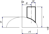
ARMC
ARMC r1, r2, l, h, d, alpha

A piece of tube starting from another tube; parameters according to the figure (penetration curves are also calculated and drawn).
The alpha value is in degrees.
r1 >= r2 + d
r1 <= l*sin(alpha) - r2*cos(alpha)
Example:

ROTY 90 CYLIND 10,1 ADDZ 6 ARMC 1, 0.9, 3, 0, 0, 45 ADDZ -1 ROTZ -90 ARMC 1, 0.75, 3, 0, 0, 90 ADDZ -1 ROTZ -90 ARMC 1, 0.6, 3, 0, 0, 135 |
ARME
ARME l, r1, r2, h, d
A piece of tube starting from an ellipsoid in the y-z plane;
parameters according to the figure (penetration lines are also calculated and drawn).
r1 >= r2+d
l >= h*sqrt(1-(r2-d)2/r12)

ELBOW
ELBOW r1, alpha, r2
A segmented elbow in the x-z plane. The radius of the arc is r1, the angle is alpha and the radius of the tube segment is r2.
The alpha value is in degrees.
r1 > r2