CUTPLANE
CUTPLANE [x [, y [, z [, side [, status]]]]]
[statement1 ... statementn]
CUTEND
CUTPLANE{2}
CUTPLANE{2} angle [, status]
[statement1 ... statementn]
CUTEND
CUTPLANE{3}
CUTPLANE{3} [x [, y [, z [, side [, status]]]]]
[statement1 ... statementn]
CUTEND
Creates a cutting plane and removes the cut parts of enclosed
shapes. CUTPLANE may have a different number of parameters.
If CUTPLANE has the following number of parameters:
0: x-y plane;
1: cutting plane goes across x axis, angle is between cutting plane and x-y plane;
2: cutting plane is parallel to z axis, crosses x axis and y axis at the given values;
3: cutting plane crosses the x, y and z axes at the given values;
4: the first three parameters are as above, with the addition of the side value as follows:
side: definition of the side to cut.0: removes parts above cutting plane (default),1: removes parts below cutting plane; in case of x-y, x-z, y-z, removes the parts in the negative direction of the axis.status: status control of the cut surfaces. If the status is not given the status is set to 1+2 automatically.status = j1 + 2*j2 + 4*j3 + 256*j9, where each j can be 0 or 1.
j1: use the attributes of the body for the generated polygons and edges.j2: generated cut polygons will be treated as normal polygons.j3: generated cut edges will be invisible.j9: vertices on the cutting plane are treated as removed.
The cut (without the side parameter) removes parts above the cutting plane.
If the first three parameters define the x-y, x-z or y-z plane (for example, 1.0, 1.0, 0.0 defines the x-y plane),
the parts in the positive direction of the third axis are removed.
Any number of statements can be added between CUTPLANE and CUTEND.
It is also possible to include CUTPLANEs in macros. CUTPLANE parameters refer to the current coordinate system.
Transformations between CUTPLANE and CUTEND have no effect on this very cutting plane,
but any successive CUTPLANEs will be transformed.
Therefore, it is recommended to use as many transformations to set up the CUTPLANE as necessary,
then delete these transformations before you define the shapes to cut.
If transformations used only to position the CUTPLANE are not removed,
you may think that the CUTPLANE is at a wrong position when, in reality, it is the shapes that have moved away.
Pairs of CUTPLANE-CUTEND commands can be nested, even within loops.
If the final CUTEND is missing, its corresponding CUTPLANE will be effective on all shapes until the end of the script.
Note
If CUTPLANE is not closed with CUTEND, all shapes may be entirely removed.
That’s why you always get a warning message about missing CUTENDs.
CUTPLANEs in macros affect shapes in the macro only, even if CUTEND is missing.
If a macro is called between CUTPLANE and CUTEND, the shapes in the macro will be cut.
Note
If you use CUTPLANE{2} with more than two parameters, then this will act like CUTPLANE.
Note
Prefer using CUTPLANE{3} instead of CUTPLANE.
If you use CUTPLANE with 5 parameters, then the 4th parameter will be omitted.
For CUTPLANE{3}, this parameter has effect independently from the 5th parameter.
Example 1:

CUTPLANE 2, 2, 4 CUTPLANE -2, 2, 4 CUTPLANE -2, -2, 4 CUTPLANE 2, -2, 4 ADD -1, -1, 0 BRICK 2, 2, 4 DEL 1 CUTEND CUTEND CUTEND CUTEND |


CUTPOLY
CUTPOLY n,
        x1, y1, ..., xn, yn
        [, x, y, z]
[statement1
statement2
...
statementn]
CUTEND
Similarly to the CUTPLANE command, parameters of CUTPOLY refer to the current coordinate system.
The polygon cannot be self-intersecting. The direction of cutting is the Z axis or an optional (x, y, z) vector can be specified.
Mirroring transformations affect the cutting direction in an unexpected way – to get a more straightforward result,
use the CUTFORM command.
Example 1:

ROTX 90
MULZ -1
CUTPOLY 3,
        0.5, 1,
        2, 2,
        3.5, 1,
        -1.8, 0, 1
DEL 1
BPRISM_ "Brick-Red", "Brick-Red", "Brick-White",
        4, 0.9, 7,
        0.0, 0.0, 15,
        6.0, 0.0, 15,
        6.0, 3.0, 15,
        0.0, 3.0, 15
CUTEND
Example 2:

a=1.0
d=0.1
GOSUB "rect_cut"
ROTX 90
GOSUB "rect_cut"
DEL 1
ROTY -90
GOSUB "rect_cut"
DEL 1
BLOCK a, a, a
CUTEND
CUTEND
CUTEND
END
"rect_cut":
    CUTPOLY 4,
            d, d,
            a-d, d,
            a-d, a-d,
            d, a-d
    RETURN
|
Example 3:

ROTX 90
FOR i=1 TO 3
    FOR j=1 TO 5
        CUTPOLY 4,
                0, 0, 1, 0,
                1, 1, 0, 1
        ADDX 1.2
    NEXT j
    DEL 5
    ADDY 1.2
NEXT i
DEL NTR()-1
ADD -0.2, -0.2, 0
BRICK 6.2, 3.8, 1
FOR k=1 TO 15
    CUTEND
NEXT k
DEL TOP
|
CUTPOLYA
CUTPOLYA n, status, d,
        x1, y1, mask1, ..., xn, yn, maskn [,
        x, y, z]
[statement1
statement2
...
statementn]
CUTEND
Similar to the CUTPOLY command, but with the possibility to control the visibility of the edges of the generated polygons.
The cutting form is a half-infinite tube with the defined polygonal cross-section.
If the end of the cutting form hangs down into the body, it will cut out the corresponding area.

status: controls the treatment of the generated cut polygons.1: use the attributes of the body for the generated polygons and edges,2: generated cut polygons will be treated as normal polygons.d: the distance between the local origin and the end of the half-infinite tube.0: means a cut with an infinite tube.maski: similar to the PRISM_ command.maski = j1 + 2*j2 + 4*j3 + 64*j7, where each j can be 0 or 1.
Example:

ROTX 90
FOR i=1 TO 3
    FOR j=1 TO 5
        CUTPOLYA 6, 1, 0,
                1, 0.15, 5,
                0.15, 0.15, 900,
                0, 90, 4007,
                0, 0.85, 5,
                0.85, 0.85, 900,
                0, 90, 4007
        ADDX 1
    NEXT j
    DEL 5
    ADDY 1
NEXT i
DEL NTR()-1
ADD -0.2, -0.2, 0
BRICK 5.4, 3.4, 0.5
FOR k=1 TO 15
    CUTEND
NEXT k
DEL TOP
CUTSHAPE
CUTSHAPE d [, status]
[statement1 statement2 ... statementn]
CUTEND
Cuts a block with “d” thickness, infinite length (both sides of the y axis) and semi-infinite height (above the xy plane).
status: controls the treatment of the generated cut polygons. If not specified (for compatibility reasons) the default value is 3.status = j1 + 2*j2, where each j can be 0 or 1.
j1: use the attributes of the body for the generated polygons and edges,j2: generated cut polygons will be treated as normal polygons.
Example:

FOR i = 1 TO 5
    ADDX 0.4 * i
    ADDZ 2.5
    CUTSHAPE 0.4
    DEL 2
    ADDX 0.4
NEXT i
DEL TOP
BRICK 4.4, 0.5, 4
FOR i = 1 TO 5
	CUTEND
NEXT i
|
CUTFORM
CUTFORM n, method, status,
        rx, ry, rz, d,
        x1, y1, mask1 [, mat1],
        ...
        xn, yn, maskn [, matn]
Similar to the CUTPOLYA command, but with the possibility
to control the form and extent of the cutting body.
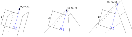
method: controls the form of the cutting body.1: prism shaped,2: pyramidal,3: wedge-shaped cutting body.
The direction of the wedge’s top edge is parallel to the Y axis and its position is in rx, ry, rz (ry is ignored).
status: Controls the extent of the cutting body and the treatment of the generated cut polygons and new edges.status = j1 + 2*j2 + 8*j4 + 16*j5 + 32*j6 + 64*j7 + 128*j8 + 256*j9, where each j can be 0 or 1.
j1: use the attributes of the body for the generated polygons and edges,j2: generated cut polygons will be treated as normal polygons,j4: define the limit of the cut (with j5),j5: define the limit of the cut (with j4):j6: generate a boolean intersection with the cutting body rather than a boolean difference. (can only be used with the CUTFORM command),j7: edges generated by the bottom of the cutting body will be invisible,j8: edges generated by the top of the cutting body will be invisible,j9: cutting shape has custom side materials (mati).j4 = 0 and j5 = 0: finite cut
j4 = 0 and j5 = 1: semi-infinite cut
j4 = 1 and j5 = 1: infinite cut
rx, ry, rz: these three coordinates define the direction of cutting if the cutting form is prism-shaped;
these three coordinates define the top point of the pyramid if the method of cutting is pyramidal;
rx-rz coordinates define the end edge of the wedge and ry is ignored if the cutting from is wedge-shaped
d: defines the distance along rx, ry, rz to the end of the cut.
If the cut is infinite, this parameter has no effect.
If the cut is finite, then the start of the cutting body will be at the local coordinate system
and the body will end at a distance of d along the direction defined by rx, ry, rz.
If the cut is semi-infinite, then the start of the cutting body will be at a distance of d
along the direction defined by rx, ry, rz, and the direction of the semi-infinite cut will be
in the opposite direction defined by rx, ry, rz.
mask: defines the visibility of the edges of the cutting body.mask = j1 + 2*j2 + 4*j3 + 8*j4 + 16*j5 + 64*j7, where each j can be 0 or 1.
j1: the polygon will create a visible edge upon entry into the body being cut (except when cutting solid body with wedge-shaped cutform, see below),j2: the lengthwise edge of the cutting form will be visible,j3: polygon will create a visible edge upon exiting the body being cut (except when cutting solid body with wedge-shaped cutform, see below),j4: the bottom edge of the cutting form will be visible,j5: the top edge of the cutting form will be visible,j7: controls the viewpoint dependent visibility of the lengthwise edge.
In case of cutting solid body with wedge-shaped cutform the values for visibility of entry-edges and exit-edges (j1 and j3) are swapped. This behavior is kept for compatibility reasons.
mati: side material of the cutting shape (when status j9 = 1)CUTFORM{2}
CUTFORM{2} n, method, status,
        rx, ry, rz, d,
        x1, y1, mask1 [, mat1],
        ...
        xn, yn, maskn [, matn]
CUTFORM{2} is an extension of the CUTFORM command
with the possibility of using inline material definition, that means materials defined in GDL script locally
also can be used next to materials defined in global material definitions.