HOTSPOT2
HOTSPOT2 x, y [, unID [, paramReference [, flags [, displayParam [, "customDescription"]]]]]

unID: the unique identifier of the hotspot in the 2D Script. Useful if you have a variable number of hotspots.paramReference: parameter that can be edited by this hotspot using the graphical hotspot based parameter editing method.displayParam: parameter to display in the information palette when editing the paramRefrence parameter.
Members of arrays can be passed as well.
customDescription: custom description string of the displayed parameter in the information palette.
When using this option, displayParam must be set as well (use paramReference for default).
See Chapter 6, Graphical Editing Using Hotspots for information on using HOTSPOT2.
HOTLINE2
HOTLINE2 x1, y1, x2, y2, unID
Status line definition between two points. Status line is a line which is recognized by the intelligent cursor but it is not visible in itself.
Can have a unique ID for associative dimensioning purpose.
HOTARC2
HOTARC2 x, y, r, startangle, endangle, unID
Status arc definition with its centerpoint at (x, y) from the angle startangle to endangle, with a radius of r.
Status arc is an arc which is recognized by the intelligent cursor but it is not visible in itself.
Can have a unique ID for associative dimensioning purpose.
LINE2
LINE2 x1, y1, x2, y2
Line definition between two points.

RECT2
RECT2 x1, y1, x2, y2
Rectangle definition by two nodes. The two points are on the diagonal of the rectangle, the sides are parallel to current X and Y axes.

POLY2
POLY2 n, frame_fill, x1, y1, ..., xn, yn
An open or closed polygon with n nodes.

n >= 2
n: number of nodes.x1, y1, ..., xn, yn: coordinates of each nodes.frame_fill: frame_fill = j1 + 2*j2 + 4*j3, where each j can be 0 or 1.
j1: draw contourj2: draw fillj3: close an open polygonPOLY2_
POLY2_ n, frame_fill, x1, y1, s1, ..., xn, yn, sn

Similar to the POLY2 command, but any of the edges can be omitted.
If si = 0, the edge starting from the (xi,yi) apex will be omitted.
If si = 1, the vertex should be shown.
si = -1 is used to define holes directly.
You can also define arcs and segments in the polyline using additional status code values.
n >= 2
n: number of nodes.x1, y1, ..., xn, yn: coordinates of each nodes.frame_fill: frame_fill = j1 + 2*j2 + 4*j3 + 8*j4 + 32*j6 + 64*j7, where each j can be 0 or 1.
j1: draw contour,j2: draw fill,j3: close an open polygon,j4: local fill orientation,j6: fill is cut fill (default is drafting fill),j7: fill is cover fill (only if j6 = 0, default is drafting fill).si: Status values:si = j1 + 16*j5 + 32*j6, where each j can be 0 or 1.
j1: next segment is visible,j5: next segment is inner line (if 0, generic line),j6: next segment is contour line (effective only if j5 is not set),-1: end of a contour.
Default line property for POLY2_ lines is 0 (generic line), the LINE_PROPERTY command has no effect on POLY2_ edges.
Additional status codes allow you to create segments and arcs in the planar polyline using special constraints.
See the section called “Additional Status Codes” for details.
POLY2_A
POLY2_A n, frame_fill, fill_pen,
        x1, y1, s1, ..., xn, yn, sn
POLY2_B
POLY2_B n, frame_fill,
        fill_pen, fill_background_pen,
        x1, y1, s1, ..., xn, yn, sn
Advanced versions of the POLY2_ command, with additional parameters: the fill pen and the fill background pen.
All other parameters are similar to those described at the POLY2_ command.
fill_pen: fill pencolor number.fill_background_pen: fill background pencolor number.Additional status codes allow you to create segments and arcs in the planar polyline using special constraints.
See the section called “Additional Status Codes” for details.
POLY2_B{2}
POLY2_B{2} n, frame_fill,
        fill_pen, fill_background_pen,
        fillOrigoX, fillOrigoY, fillAngle,
        x1, y1, s1, ..., xn, yn, sn
Advanced version of the POLY2_B command where the hatching origin and direction can be defined.
frame_fill: frame_fill = j1 + 2*j2 + 4*j3 + 8*j4 + 16*j5 + 32*j6 + 64*j7, where each j can be 0 or 1.
j1: draw contourj2: draw fillj3: close an open polygonj4: local fill orientationj5: global fill origin (effective only if j4 is set)j6: fill in cut category (distinctive with j7, drafting category if none is set)j7: fill in cover category (distinctive with j6, drafting category if none is set).fillOrigoX: X coordinate of the fill origin.fillOrigoY: Y coordinate of the fill origin.fillAngle: direction angle of fill.Additional status codes allow you to create segments and arcs in the planar polyline using special constraints.
See the section called “Additional Status Codes” for details.
POLY2_B{3}
POLY2_B{3} n, frame_fill,
        fill_pen, fill_background_pen,
        fillOrigoX, fillOrigoY,
        mxx, mxy, myx, myy, x1, y1, s1, ..., xn, yn, sn
Advanced version of the POLY2_B command, where the orientation of the fill can be defined using a matrix.
frame_fill: frame_fill = j1 + 2*j2 + 4*j3 + 8*j4 + 16*j5 + 32*j6 + 64*j7 + 128*j8, where each j can be 0 or 1.
j1-j7: similar as for previous POLY2_ commands,
j8: use sloped fill.mxx, mxy, myx, myy: if j8 is set, this matrix defines the orientation of the fill.Additional status codes allow you to create segments and arcs in the planar polyline using special constraints.
See the section called “Additional Status Codes” for details.
POLY2_B{4}
POLY2_B{4} n, frame_fill,
        fill_pen, fill_background_pen,
        fillOrigoX, fillOrigoY,
        mxx, mxy, myx, myy,
        gradientInnerRadius,
        x1, y1, s1, ..., xn, yn, sn
Advanced version of POLY2_ B{3}, where the inner radius of radial gradient fill can be set.
gradientInnerRadius: inner radius of the gradient in case radial gradient fill is selected for the polygon.POLY2_B{5}
POLY2_B{5} n, frame_fill, fillcategory, distortion_flags,
        fill_pen, fill_background_pen,
        fillOrigoX, fillOrigoY,
        mxx, mxy, myx, myy,
        gradientInnerRadius,
        x1, y1, s1, ..., xn, yn, sn
Advanced version of POLY2_ B{4}, where fill distortion can be controlled in an enhanced way.
frame_fill: frame_fill = j1 + 2*j2 + 4*j3, where each j can be 0 or 1.
j1: draw contourj2: draw fillj3: close an open polygon.fillcategory: 0: Draft,1: Cut,2: Cover.distortion_flags: distortion_flags = j1 + 2*j2 + 4*j3 + 8*j4 + 16*j5 + 32*j6 + 64*j7, where each j can be 0 or 1.
The valid value for distortion_flags is between 0 and 127. Don’t use value out of this range.
j1: the fill origin’s X coordinate is the global origin’s X coordinate, meaningful only when j4 is set.
The fillOrigo is the origin (0,0) projected on the line of the (mxx, mxy) vector,
j2: the fill origin’s Y coordinate is the global origin’s Y coordinate, meaningful only when j4 is set,j3: create circular distortion using the innerRadius parameter,j4: use local orientation, use the distortion matrix (mij parameters),j5: (effective for symbol fills only) reset the pattern’s X size to the defined X vector’s length (mxx, mxy),j6: (effective for symbol fills only) reset the pattern’s Y size to the defined Y vector’s length (myx, myy),j7: (effective for symbol fills only) keep proportion of symbol fill pattern; effective only if one of j5 and j6 is set.innerRadius: radius for circular fill distortion;
the origin of the base circle will be placed on the Y fill axis in the (0, -innerRadius) position.
POLY2_B{6}
POLY2_B6  n, frame_fill, fillcategory, distortion_flags,
   fill_pen, fill_background_pen,
   fillOrigoX, fillOrigoY,
   mxx, mxy, myx, myy,
   gradientInnerRadius,
   x1, y1, s1, pen1, linetype1, ..., xn, yn, sn, penn, linetypen
Advanced version of POLY2_B{5}, where contour attributes (pen and linetype) can be controlled individually for each contour segment.
peni: pen index of the contour line starting from control point i.linetypei: line type index of the contour line starting from control point i.Compatibility: introduced in ARCHICAD 21.
ARC2
ARC2 x, y, r, alpha, beta
An arc with its centerpoint at (x, y) from the angle alpha to beta, with a radius of r.
Alpha and beta are in degrees.

CIRCLE2
CIRCLE2 x, y, r
A circle with its center at (x, y), with a radius of r.

SPLINE2
SPLINE2 n, status, x1, y1,
        angle1, ..., xn, yn, anglen

Spline, with n control points. The tangent of the spline in the control point (xi, yi) is defined by anglei, the angle with the x axis in degrees.
n >= 2
si: Status values:0: default,1: closed spline; the last and first nodes of the spline will become connected, thus closing the spline,2: automatically smoothed spline; the angle parameter value of the nodes between the first and the last node is not used when generating the spline. An internal autosmoothing algorithm is used.

Example 2:

n = 5
FOR i = 1 TO n
    SPLINE2 4, 0,
            0.0, 2.0, 135.0,
            -1.0, 1.8, 240.0,
            -1.0, 1.0, 290.0,
            0.0, 0.0,  45.0
    MUL2 -1.0, 1.0
    SPLINE2 4, 0,
            0.0, 2.0, 135.0,
            -1.0, 1.8, 240.0,
            -1.0, 1.0, 290.0,
            0.0, 0.0,  45.0
    DEL 1
    SPLINE2 4, 0,
            0.0, 2.0, 100.0,
            0.0, 2.5,   0.0,
            0.0, 2.4, 270.0,
            0.0, 2.0, 270.0
    ADD2 2.5, 0
NEXT i
|
SPLINE2A
SPLINE2A n, status, x1, y1, angle1, length_previous1, length_next1,
        ...
        xn, yn, anglen, length_previousn,
        length_nextn
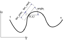
Extension of the SPLINE2 command (Bézier spline), used mainly in automatic 2D script generation because of its complexity.
For more details, see “Lines / Drawing Splines” in the Documentation chapter of the Help.
si: Status values:0: default,1: closed spline; the last and first nodes of the spline will become connected, thus closing the spline,2: automatically smoothed spline; the angle, length_previousi and length_nexti parameter values of the nodes between the first and the last node are not used when generating the spline. An internal autosmoothing algorithm is used.
xi, yi: control point coordinates.length_previousi, length_nexti: tangent lengths for the previous and the next control points.anglei: tangent direction angle.Example:

SPLINE2A 9, 2,
        0.0, 0.0, 0.0, 0.0, 0.0,
        0.7, 1.5,  15, 0.9, 1.0,
        1.9, 0.8,  72, 0.8, 0.3,
        1.9, 1.8, 100, 0.3, 0.4,
        1.8, 3.1,  85, 0.4, 0.5,
        2.4, 4.1, 352, 0.4, 0.4,
        3.5, 3.3, 338, 0.4, 0.4,
        4.7, 3.7,  36, 0.4, 0.8,
        6.0, 4.6,   0, 0.0, 0.0
|
PICTURE2
PICTURE2 expression, a, b
PICTURE2{2}
PICTURE2{2} expression, a, b, mask
Can be used in 2D similarly to the PICTURE command in 3D.
The mask values are the following for PICTURE2{2}:
- 0 transparent pixels are displayed as full white
- 1 transparent pixels are displayed as transparent
The expression parameter can either mean a file name (string), or an index (integer) of a picture stored in the library part.
A 0 index is a special value, it refers to the preview picture of the library part.
Other pictures can only be stored in library parts when saving the project or selected elements containing pictures as GDL objects.