The drawing elements presented in this section can be used in 3D scripts,
allowing you to define points, lines, arcs, circles and planar polygons in the three-dimensional space.
HOTSPOT
HOTSPOT x, y, z [, unID [, paramReference [, flags [, displayParam [, customDescription]]]]]
A 3D hotspot in the point (x, y, z).
unID: the unique identifier of the hotspot in the 3D script. It is useful if you have a variable number of hotspots.paramReference: parameter that can be edited by this hotspot using the graphical hotspot based parameter editing method.displayParam: parameter to display in the information palette when editing the paramRefrence parameter. Members of arrays can be passed as well.customDescription: custom description of the displayed parameter in the information palette.
When using this option, displayParam must be set as well (use paramReference for default).
See Chapter 6, Graphical Editing Using Hotspots for using HOTSPOT.
HOTLINE
HOTLINE x1, y1, z1, x2, y2, z2, unID
A status line segment between the points P1 (x1,y1,z1) and P2 (x2,y2,z2).
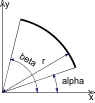
HOTARC
HOTARC r, alpha, beta, unID
A status arc in the x-y plane with its center at the origin from angle alpha to beta with a radius of r.
Alpha and beta are in degrees.
LIN_
LIN_ x1, y1, z1, x2, y2, z2
A line segment between the points P1 (x1,y1,z1) and P2 (x2,y2,z2).
RECT
RECT a, b
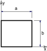
A rectangle in the x-y plane with sides a and b.
a >= 0, b >= 0
POLY
POLY n, x1, y1, ..., xn, yn

A polygon with n edges in the x-y plane. The coordinates of nodei are (xi, yi, 0).
n >= 3
POLY_
POLY_ n, x1, y1, s1, ..., xn, yn, sn
Similar to the normal POLY statement, but any of the edges can be omitted.
si: status code that allows you to control the visibility of polygon edges and side surfaces.
You can also define holes and create segments and arcs in the polyline using special constraints.
si = 0: the edge starting from the (xi,yi) apex will be omitted,si = 1: the edge will be shown,si = -1: is used to define holes directly.Additional status codes allow you to create segments and arcs in the planar polyline using special constraints.
See the section called “Additional Status Codes” for details.
 |
 |
n >= 3
PLANE
PLANE n, x1, y1, z1, ..., xn, yn, zn
A polygon with n edges on an arbitrary plane. The coordinates of nodei are (xi, yi, zi).
The polygon must be planar in order to get a correct shading/rendering result, but the interpreter does not check this condition.
n >= 3
PLANE_
PLANE_ n, x1, y1, z1, s1, ..., xn, yn, zn, sn
Similar to the PLANE command,
but any of the edges can be omitted as in the POLY_ command.
Additional status codes allow you to create segments and arcs in the planar polyline using special constraints.
See the section called “Additional Status Codes”.
n >= 3
CIRCLE
CIRCLE r
A circle in the x-y plane with its center at the origin and with a radius of r.

ARC
ARC r, alpha, beta
An arc (in Wireframe mode) or sector (in other modes) in the x-y plane with its center at the origin from angle alpha to beta with a radius of r.
alpha and beta are in degrees.