GDL is capable of performing specialized 3D operations between
solids represented by groups. These operations can be one of the
following:
ADDGROUP
|
forming the Boolean union of two solids |
 |
SUBGROUP
|
forming the Boolean difference of two solids |
 |
ISECTGROUP
|
forming the Boolean intersection of two solids |
 |
ISECTLINES
|
calculating the intersection lines of two solids |
 |
SWEEPGROUP
|
sweeping a solid along a vector |
 |
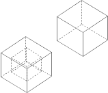
A GDL solid is composed of one or more lumps that appear as separated bodies in the model.
A lump has exactly one outer shell and may contain voids. (Voids can be described as “negative” inner shells inside a lump.)
The solid in the drawing below is composed of two lumps in such a way that one of them contains a void.

GDL bodies such as BLOCK, SPHERE, etc., appear as outer shells in groups.
By means of the following construction the user is capable of putting more than one shell in a solid (note the BODY -1 statement):
GROUP "myGroup"
    BLOCK 1,1,1
    BODY -1
    ADDX 1
    BLOCK 1,1,1
ENDGROUP
The above solid contains two lumps; each of them is composed of one shell.
Voids can be defined by means of primitives, or can occur as a result of a Boolean difference
(e.g. subtracting a small cube from the middle of a big one).
See also the section called “Primitive Elements”.
Although group operations are intended to work with solid objects, they can be applied to surfaces, wireframes or hybrid models, too.
(Hybrid models are basically surfaces that may contain edges without neighboring faces.)
The result of the operations on such models are summarized in the following tables:
Table 4.1. Union (base » tool)
| solid base | surface base | wireframe base | hybrid base | |
| solid tool | solid result | surface result (merging) | wireframe result (merging) | hybrid result (merging) |
| surface tool | surface result (merging) | surface result (merging) | hybrid result (merging) | hybrid result (merging) |
| wireframe tool | wireframe result (merging) | hybrid result (merging) | wireframe result (merging) | hybrid result (merging) |
| hybrid tool | hybrid result (merging) | hybrid result (merging) | hybrid result (merging) | hybrid result (merging) |
Table 4.2. Difference (basetool)
| solid base | surface base | wireframe base | hybrid base | |
| solid tool | solid result | surface result | wireframe result | hybrid result |
| surface tool | surface base (no effect) | surface base (no effect) | hybrid base (no effect) | hybrid base (no effect) |
| wireframe tool | wireframe base (no effect) | hybrid base (no effect) | wireframe base (no effect) | hybrid base (no effect) |
| hybrid tool | hybrid base (no effect) | hybrid base (no effect) | hybrid base (no effect) | hybrid base (no effect) |
Table 4.3. Intersection (base « tool)
| solid base | surface base | wireframe base | hybrid base | |
| solid tool | solid result | surface result | wireframe result | hybrid result |
| surface tool | surface result | empty result | empty result | empty result |
| wireframe tool | wireframe result | empty result | empty result | empty result |
| hybrid tool | hybrid result | empty result | empty result | empty result |
Table 4.4. Intersection lines (base « tool)
| solid base | surface base | wireframe base | hybrid base | |
| solid tool | wireframe result | wireframe result | empty result | wireframe result |
| surface tool | wireframe result | empty result | empty result | empty result |
| wireframe tool | empty result | empty result | empty result | empty result |
| hybrid tool | wireframe result | empty result | empty result | empty result |
Table 4.5. Sweeping
| solid | surface | wireframe | hybrid |
| valid result | surface base (no effect) | wireframe base (no effect) | hybrid base (no effect) |
Surfaces can be explicitly generated by using the MODEL SURFACE command,
or implicitly by leaving out non-neighboring face polygons from the model.
Wireframes are produced either by using the MODEL WIRE statement or by defining objects without face polygons.
Hybrid models can only be generated indirectly by leaving out neighboring face polygons from the model.
In the majority of the cases the required model is solid.
GDL bodies appear as shells in group definitions, so in order to achieve fast and reliable operation,
the geometric correctness of the generated shells is a critical issue.
Handling degenerated objects loads the GDL engine and causes the desired operation to take more time to complete.
The main rule to be considered regarding the efficient use of GDL group operations can be summarized as follows:
model by conforming to existing physical presence of spatial objects. In practice this can be expressed by the following guidelines:
According to the above, these rules are to be followed for shells (defined by bodies), not for solids (defined by groups).
(The solid produced by the script in the Group construction above is modeled properly,
since the constituent shells touch each other but the shells, themselves, are geometrically correct.)
GROUP – ENDGROUP
GROUP "name"
    [statement1 ... statementn]
ENDGROUP
Group definition. All bodies between the corresponding GROUP – ENDGROUP statements will be part of the “name” group.
Groups are not actually generated (placed), they can be used in group operations or placed explicitly using the PLACEGROUP command.
Group definitions cannot be nested, but macro calls containing group definitions and PLACEGROUP commands using other groups can be included.
Group names must be unique inside the current script.
Transformations, cutplanes outside the group definition have no effect on the group parts;
transformations, cutplanes used inside have no effect on the bodies outside the definition.
Group definitions are transparent to attribute DEFINEs and SETs (pens, materials, fills);
attributes defined/set before the definition and those defined/set inside the definition are all effective.
ADDGROUP
ADDGROUP (g_expr1, g_expr2)
ADDGROUP{2} (g_expr1, g_expr2, edgeColor, materialId, materialColor [, operationStatus])
ADDGROUP{3} (g_expr1, g_expr2, edgeColor, materialId, materialColor [, operationStatus])
SUBGROUP
SUBGROUP (g_expr1, g_expr2)
SUBGROUP{2} (g_expr1, g_expr2, edgeColor, materialId, materialColor [, operationStatus])
SUBGROUP{3} (g_expr1, g_expr2, edgeColor, materialId, materialColor [, operationStatus])
ISECTGROUP
ISECTGROUP (g_expr1, g_expr2)
ISECTGROUP{2} (g_expr1, g_expr2, edgeColor, materialId, materialColor [, operationStatus])
ISECTGROUP{3} (g_expr1, g_expr2, edgeColor, materialId, materialColor [, operationStatus])
g_expr1: identifier of the base group.g_expr2: identifier of the tool group.edgeColor: the color of the new edge when it differs from 0.materialId: the material of the new face when it differs from 0.materialColor: the color of the new face when the materialId is 0 and it differs from 0.operationStatus: status control of the operation.operationStatus = j1 + 2*j2, where each j can be 0 or 1.
j1: generated new edges will be invisible.j2: cut polygons of the result inherit material and texture projection from the corresponding polygons of the tool group.ISECTLINES
ISECTLINES (g_expr1, g_expr2)
Group operations: addition, subtraction, intersection, intersection lines.
The return value is a new group, which can be placed using the PLACEGROUP command,
stored in a variable or used as a parameter in another group operation.
Group operations can be performed between previously defined groups or groups result from any other group operation.
g_expr1, g_expr2 are group type expressions.
Group type expressions are either group names (string expressions)
or group type variables or any combination of these in operations which result in groups.
Note that the operations ADDGROUP, ISECTGROUP and ISECTLINES are symmetric in their parameterization while the order of parameter matters for SUBGROUP.
PLACEGROUP
PLACEGROUP g_expr
Placing a group is the operation in which bodies are actually generated.
Cutplanes and transformations are effective, the group expression is evaluated and the resulting bodies are stored in the 3D data structure.
KILLGROUP
KILLGROUP g_expr
Clears the bodies of the specified group from the memory.
After a KILLGROUP operation the group becomes empty. The names of killed groups cannot be reused in the same script.
Clearing is executed automatically at the end of the interpretation or when returning from macro calls.
For performance reasons this command should be used when a group is no longer needed.
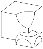
Example:

GROUP "box"
    BRICK 1, 1, 1
ENDGROUP
GROUP "sphere"
    ADDZ 1
    SPHERE 0.45
    DEL 1
ENDGROUP
GROUP "semisphere"
    ELLIPS 0.45, 0.45
ENDGROUP
GROUP "brick"
    ADD -0.35, -0.35, 0
    BRICK 0.70, 0.70, 0.35
    DEL 1
ENDGROUP
! Subtracting the "sphere" from the "box"
result_1=SUBGROUP("box", "sphere")
! Intersecting the "semisphere" and the "brick"
result_2=ISECTGROUP("semisphere", "brick")
! Adding the generated bodies
result_3=ADDGROUP(result_1, result_2)
PLACEGROUP result_3
KILLGROUP "box"
KILLGROUP "sphere"
KILLGROUP "semisphere"
KILLGROUP "brick"
|
SWEEPGROUP
SWEEPGROUP (g_expr, x, y, z)
Returns a group that is created by sweeping the group parameter along the given direction.
The command works for solid models only.
SWEEPGROUP{2} (g_expr, x, y, z)
The difference between SWEEPGROUP and SWEEPGROUP{2} is that in the former case the actual transformation matrix is applied again
to the direction vector of the sweeping operation with respect to the current coordinate system.
(In the case of SWEEPGROUP, the current transformation is applied to the direction vector twice with respect to the global coordinate system.)
SWEEPGROUP{3} (g_expr, x, y, z, edgeColor, materialId, materialColor, method)
This version adds a new method selection to SWEEPGROUP{2} and works for surface models also.
edgeColor: the color of the new edge when it differs from 0.materialId: the material of the new face when it differs from 0.materialColor: the color of the new face when the materialId is 0 and it differs from 0.method: controls the ending shape of the resulting body.0: same as SWEEPGROUP{2}, both ends come from the originating body,1: the start comes from the originating body, the sweep end is flatSWEEPGROUP{4} (g_expr, x, y, z, edgeColor, materialId, materialColor, method, status)
This version adds a new status parameter to SWEEPGROUP{3}.
status: Controls attributes of the result.status = 2*j2, where each j can be 0 or 1.
j2: Keep per-polygon texture mapping parameters on the sweeped result (see the PGON command for details).SWEEPGROUP{5} (g_expr, x, y, z, edgeColor, materialId, materialColor, method, status)
Compatibility: introduced in ARCHICAD 22.
SWEEPGROUP{5} is an extension of the SWEEPGROUP{4} command with the possibility of using inline material definition, that means materials defined in GDL script locally also can be used next to materials defined in global material definitions.
Example:

GROUP "the_sphere"
    SPHERE 1
ENDGROUP
PLACEGROUP SWEEPGROUP{2} ("the_sphere", 2, 0, 0)
ADDX 5
PLACEGROUP SWEEPGROUP{3} ("the_sphere", 2, 0, 0, 4, 0, 4, 1)
del 1
CREATEGROUPWITHMATERIAL
CREATEGROUPWITHMATERIAL (g_expr, repl_directive, pen, material)
Returns a group that is created by replacing all pens and/or materials in group g_expr.
g_expr: group expression identifying the base group.repl_directive: repl_directive = j1 + 2*j2 + 4*j3 + 8*j4, where each j can be 0 or 1.
j1: replace pen,j2: replace material,j4: make edges invisible.pen: replacement pen index.material: replacement material index.