This section discusses the various special options related to the creation of Door/Window library elements.
Once a door/window is inserted into a wall, the default position of these library parts’ coordinate system is rotated
so that the x-y plane is vertical and the z axis points horizontally into the wall.
The origin is placed on the bottom center of the wall opening, on the exterior side of the wall.
This way, doors/windows can be easily modeled by elements in the x-y plane. See the illustrations below.
 |
 |
Because of the special behavior of these library parts,
the 2D symbol is generated from a special built-in projection otherwise not accessible by users (an upside-down side view from a 90 degree direction).
The symbol and the 3D shape are fitted to the Door/Window origin by the lower (y) center (x) of the bounding box,
but no adjustment is made along the z axis to enable users to design doors/windows extending beyond the wall in either z direction.
Considering these rules, here are some hints that will help you construct doors/windows that will work properly:
- When constructing the door/window in the floor plan window,
visualize it as if you are looking at it from the inside of the wall it will be inserted into. - Think of the project zero level as the external surface of the wall.
- Elements that should be inside the wall, like the window frame, should be above the zero level.
- Door panels opening to the outside should be below the zero level.
A door is correctly defined if its insertion works as follows: clicking to the right of the insertion point means
that the door leaf will open to the same side on the right.
A window is correctly defined if, upon insertion, the side that is clicked corresponds to the outer side.
An opening position can take one of 8 forms.
These are represented by three global variables in GDL:
Usually each part of the window should react in a different way to these conditions.
The specification must be clear on deciding how the parts of the object should,
or should not act.
E.g. a door leaf moves with these transformations, but the cavity closure does not.
To keep the library part consistent, several transformations should be used for these combinations.
When changing the reveal side (flipping), the library part is mirrored and dragged back by the value of the nominal frame thickness.
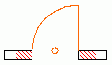
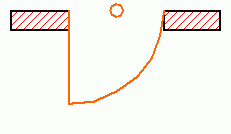
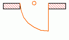
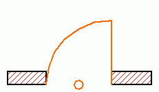
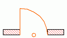
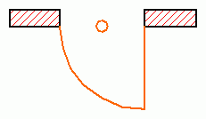
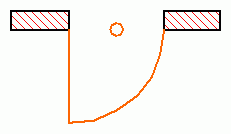
Illustration of the 8 states with a simplified door – the little circle flags the origin.
| Global variables 1. | Example drawing 1. | Global variables 2. | Example drawing 2. |
|---|---|---|---|
WIDO_REVEAL_SIDE = 0 SYMB_MIRRORED = 1 SYMB_ROTANGLE = 0 |
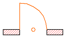 |
WIDO_REVEAL_SIDE = 0 SYMB_MIRRORED = 0 SYMB_ROTANGLE = 0 |
 |
WIDO_REVEAL_SIDE = 1 SYMB_MIRRORED = 0 SYMB_ROTANGLE = 180 |
 |
WIDO_REVEAL_SIDE = 1 SYMB_MIRRORED = 1 SYMB_ROTANGLE = 180 |
 |
WIDO_REVEAL_SIDE = 1 SYMB_MIRRORED = 0 SYMB_ROTANGLE = 0 |
 |
WIDO_REVEAL_SIDE = 1 SYMB_MIRRORED = 1 SYMB_ROTANGLE = 0 |
 |
WIDO_REVEAL_SIDE = 0 SYMB_MIRRORED = 1 SYMB_ROTANGLE = 180 |
 |
WIDO_REVEAL_SIDE = 0 SYMB_MIRRORED = 0 SYMB_ROTANGLE = 180 |
 |
Sample code undoing the automatic transformations done by ARCHICAD:
! 2D script
bRotated = round_int (SYMB_ROTANGLE) = 180
if bRotated then
	rot2 180
endif
if SYMB_MIRRORED then
	mul2 -1, 1
endif
if WIDO_REVEAL_SIDE exor bRotated then
	add2 0, WALL_THICKNESS
endif

! 3D script
bRotated = round_int (SYMB_ROTANGLE) = 180
if bRotated then
	roty 180
endif
if SYMB_MIRRORED then
	mulx -1
endif
if WIDO_REVEAL_SIDE exor bRotated then
	addz -WALL_THICKNESS
endif
Note that though flipping and mirroring is possible for all doors and windows,
it is incorrect in manufacturer libraries where a library part models a real window – which, of course, cannot be turned inside out.
In this case the script should undo the mirroring done by ARCHICAD.
When creating Door/Window type library parts, several possibilities exist, presenting different problems:
This is the easiest and most straightforward way of creating doors and windows.
The use of simple GDL commands such as PRISM_ or RECT is recommended.
If you want to match the surface materials of door/window elements to those of the wall,
the bottom surface of the elements should match the outside, and the top surface the inside of the wall.
You can achieve this from your scripts using the WALL_MAT_A, WALL_MAT_B and WALL_MAT_EDGE global variables
representing the surface materials of the wall into which the door/window is placed.
In the 2D script, the WALL_SECT_PEN, WALL_FILL_PEN and WALL_FILL global variables can be useful,
as these give you the pen numbers of the wall contour and fill plus the index number of the fill of the wall
on the floor plan into which the door/window is placed. With composite walls, you have to use the corresponding global variables.
See Wall parameters – available for Doors/Windows for details.
The object libraries come with a large set of door/window macros.
These GDL scripts contain common building elements which are used by many doors/windows in the library.
There are macros for generating commonly-used frames, panels and many other types of door/window parts.
Open some door/window library parts to see what kind of macros they call and what type of parts those macros generate.
Example:

a=0.9: b=1.5: c=0.1: d=0.08
e=0.08: f=0.9: g=0.03: h=3
PRISM_ 10, c,
        -a/2, 0, 15, a/2, 0, 15,
        a/2, b, 15, -a/2, b, 15,
        -a/2, 0, -1,
        -a/2+d, d, 15, a/2-d, d, 15,
        a/2-d, b-d, 15, -a/2+d, b-d, 15,
        -a/2+d, d, -1
ADD -a/2+d, f, 0
BRICK a-2*d, e, c
ADD -g/2, -f+d, c/2
GOSUB 1
ADDZ -g
GOSUB 1
DEL 2
MATERIAL "Glass - Blue"
ADD 0, -f+d, c/2
RECT a-2*d, f-d
ADDY f-d+e
RECT a-2*d, b-f-e-d
END

1:
    FOR i=1 TO h-1
        ADDX (a-2*d)/3
        BLOCK g, f-d, g
        ADDY f+e-d
        BLOCK g, b-f-d-e, g
        DEL 1
    NEXT i
    DEL h-1
    RETURN
When working with doors/windows, it is important to know that placing a door/window always cuts a rectangular hole into the wall.
The size of this hole is determined by the A and B parameters of the door/window library part.
However, when the door/window is not rectangular in elevation, it does not entirely fill the cut rectangular hole.
The solution to this is to use the WALLHOLE or WALLNICHE command to define a polygon shape to be cut into the wall where the door/window is placed.
There are two solutions for this:
The 3D script has to contain parts that generate those parts of the wall that fill the hole between the door/window body and the edges of the rectangular wall cut.
In this case, special attention must be paid to the visibility of the edges of these fillings.- With the WALLHOLE or WALLNICHE command, you can define a polygon shape to be cut into the wall where the door/window is placed.

WALLHOLE
WALLHOLE n, status,
        x1, y1, mask1,
        ...
        xn, yn, maskn
        [, x, y, z]
n: the number of polygon nodes.status: 1: use the attributes of the body for the generated polygons and edges,2: generated cut polygons will be treated as normal polygons.xi, yi: cross-section polygon coordinates.
maski = j1 + 2*j2 + 4*j3 + 64*j7, where each j can be 0 or 1.x, y, z: optional direction vector (default is door/window Z axis).
This command can be used in doors’/windows’ 3D script to cut custom hole(s) in the wall they are placed into.
During the 3D generation of the current wall,
the 3D script of all its doors/windows is interpreted without model generation to collect the WALLHOLE commands.
If they exist, the current wall will be cut using an infinite tube with the polygonal cross-section and direction defined in the script.
There can be any number of WALLHOLEs for any door/window, so it is possible to cut more holes for the same door/window,
even intersecting ones.
If at least one WALLHOLE command is interpreted in a door/window 3D script, no rectangular opening will be generated for that door/window.
Note
The 3D reveal will not be generated automatically for custom holes, you have to generate it from the script.
The hole customized this way will only be visible in 3D, because WALLHOLE commands do not have any effect in 2D.
A 2D representation can be scripted if needed (used with framing in plan off).
The use of convex polygonal cross-sections is recommended; using concave polygons may result in strange shadings/renderings or cut errors.
Convex polygons can be combined to obtain concave ones.
Mirroring transformations affect the cutting direction in an unexpected way – to get a more straightforward result,
use the WALLNICHE command.
Example 1:

RESOL 72
l1 = 2.7: l2=1.2
h1=2.1: h2=0.3: h3=0.9
r = ((l1/2)^2+h2^2)/(2*h2)
a = ATN((l1/2)/(r-h2))
WALLHOLE 5, 1,
        -l1/2, h3,    15,
        l1/2,  h3,    15,
        l1/2,  h1-h2, 13,
        0,     h1-r,  915,
        0, 2*a, 4015
WALLHOLE 4, 1,
        l1/2-l2, 0,  15,
        l1/2,    0,  15,
        l1/2,    h3, 15,
        l1/2-l2, h3, 15
Example 2:

WALLHOLE 5, 1,
        -0.45, 0, 15,
        0.45, 0, 15,
        0.45, 1.5, 15,
        0, 1.95, 15,
        -0.45, 1.5, 15
PRISM_ 12, 0.1,
        -0.45, 0, 15,
        0.45, 0, 15,
        0.45, 1.5, 15,
        0, 1.95, 15,
        -0.45, 1.5, 15,
        -0.45, 0, -1,
        -0.35, 0.1, 15,
        0.35, 0.1, 15,
        0.35, 1.45, 15,
        0, 1.80, 15,
        -0.35, 1.44, 15,
        -0.35, 0.1, -1
|
WALLNICHE
WALLNICHE n, method, status,
        rx, ry, rz, d,
        x1, y1, mask1, [mat1,]
        ...
        xn, yn, maskn[, matn]
Similar to the CUTFORM command.
method: Controls the form of the cutting body:1: prism shaped,2: pyramidal,3: wedge-shaped cutting body.The direction of the wedge’s top edge is parallel to the Y axis and its position is in rx, ry, rz (ry is ignored).
status: Controls the extent of the cutting body and the treatment of the generated cut polygons and new edges.status = j1 + 2*j2 + 8*j4 + 16*j5 + 32*j6 + 64*j7 + 128*j8 + 256*j9, where each j can be 0 or 1.j1: use the attributes of the body for the generated polygons and edges,j2: generated cut polygons will be treated as normal polygons,j4: define the limit of the cut (with j4),j5: define the limit of the cut (with j5),j6: generate a boolean intersection with the cutting body rather than a boolean difference.(can only be used with the CUTFORM command),
j7: edges generated by the bottom of the cutting body will be invisible,j8: edges generated by the top of the cutting body will be invisible.j9: cutting shape has custom side materials (mati).j4 = 0 and j5 = 0: finite cut,
j4 = 0 and j5 = 1: semi-infinite cut,
j4 = 1 and j5 = 1: infinite cut,
rx,ry,rz: defines the direction of cutting if the cutting form is prism-shaped,
or the top of the pyramid if the method of cutting is pyramidal.
d: defines the distance along rx,ry,rz to the end of the cut. If the cut is infinite, this parameter has no effect.
If the cut is finite, then the start of the cutting body will be at the local coordinate system
and the body will end at a distance of d along the direction defined by rx,ry,rz.
If the cut is semi-infinite, then the start of the cutting body will be at a distance of d
along the direction defined by rx,ry,rz and the direction of the semi-infinite cut will be
in the opposite direction defined by rx,ry,rz.
mati: side material of the cutting shape (when status j9 = 1)mask: Defines the visibility of the edges of the cutting body.
j1: the polygon will create a visible edge upon entry into the body being cut,j2: the lengthwise edge of the cutting form will be visible,j3: the polygon will create a visible edge upon exiting the body being cut,j4: the bottom edge of the cutting form will be visible,j5: the top edge of the cutting form will be visible,j7: controls the viewpoint dependent visibility of the lengthwise edge.When placing doors/windows into curved walls, the sides of the hole cut into the wall can vary according to the picture below.

The hole in the wall on the left is created when the program automatically cuts the hole for the door/window.
In this case the sides will be of radial direction.
On the right, the hole is cut using the WALLHOLE command in the 3D Script of the door/window object.
The object itself needs to be written by taking these factors into consideration.
Another thing to consider is whether the door/window placed into the curved wall is a straight or a curved one.

In the case of a straight door/window, as on the left above,
the thickness and width of the object and the thickness of the wall are closely related,
since above a certain dimension the object would fall outside of the wall.
When using true curved doors/windows, this problem doesn’t occur.
Example:
Window with a frame following the curve of the wall

RESOL 72
ROTX -90 : MULY -1
C= 0.12 : Z=360*A/(2*WIDO_ORIG_DIST*PI)
Y= 360*C/(2*WIDO_ORIG_DIST*PI) : A1= 270+Z/2 : A2=270-Z/2
GOSUB "curved_horizontal_frame"
ADDZ B
MULZ -1
GOSUB "curved_horizontal_frame"
DEL 2
ADDZ C
GOSUB "vertical_frame"
MULX -1
GOSUB "vertical_frame"
END
"curved_horizontal_frame":
    PRISM_ 9, C,
            cos(A2)*R_, SIN(A2)*R_+R_, 11,
            cos(A2+Y)*R_, sin(A2+Y)*R_+R_, 13,
            0, R_, 900,
            0, Z-2*Y, 4009,
            cos(A1)*R_, sin(A1)*R_+R_, 11,
            cos(A1)*(R_-0.1), sin(A1)*(R_-0.1)+R_, 11,
            cos(A1-Y)*(R_-0.1), sin(A1-Y)*(R_-0.1)+R_, 13,
            0, -(Z-2*Y), 4009,
            cos(A2)*(R_-0.1), sin(A2)*(R_-0.1)+R_, 11
    RETURN
"vertical_frame":
    PRISM_ 4, B-2*C,
            cos(A2)*R_,         sin(A2)*R_+R_, 10,
            cos(A2+Y)*R_,       sin(A2+Y)*R_+R_, 15,
            cos(A2+Y)*(R_-0.1), sin(A2+Y)*(R_-0.1)+R_, 10,
            cos(A2)*(R_-0.1),   sin(A2)*(R_-0.1)+R_, 10
    RETURN
The general guidelines given for rectangular doors/windows in curved walls applies here, too.
Example:

wFrame=0.1: wDivider=0.025
Z=A/2-SQR(2)*wFrame: Y=A/2-SQR(2)*wFrame-wDivider
ADDY A/2
WALLHOLE 4, 1,
        0,    -A/2, 15,
        A/2,  0,    15,
        0,    A/2,  15,
        -A/2, 0,    15
PRISM_ 10, 0.1,
        0,    -A/2, 15,
        A/2,  0,    15,
        0,    A/2,  15,
        -A/2, 0,    15,
        0,    -A/2, -1,
        0,    -Z,   15,
        Z,    0,    15,
        0,    Z,    15,
        -Z,   0,    15,
        0, -  Z,    -1
ADDZ 0.02
GOSUB "cross_divider"
ADDZ 0.03
GOSUB "cross_divider"
ADDY -Z
SET MATERIAL "Glass - Blue"
ROTZ 45
RECT SQR(2)*Z, SQR(2)*Z
END
"cross_divider":
    PRISM_ 16, 0.03,
            0, -Z, 15,
            wDivider, -Y, 15,
            wDivider, -wDivider, 15,
            Y, -wDivider, 15,
            Z, 0, 15,
            Z, wDivider, 15,
            wDivider, wDivider, 15,
            wDivider, Y, 15,
            0, Z, 15,
            -wDivider, Y, 15,
            -wDivider, wDivider, 15,
            -Y, wDivider, 15,
            -Z, 0, 15,
            -Y, -wDivider, 15,
            -wDivider, -wDivider, 15,
            -wDivider, -Y, 15
    RETURN
Placing a door/window cuts a rectangular hole into the wall by default.
The size of this hole in 2D is determined by the A parameters of the door/window library part.
Implementing custom reveals or cavity closures requires cutting custom shaped holes in the wall or extending it a bit in the floor plan view.
A correct solution for this issue can be achieved by using the WALLHOLE2, WALLBLOCK2, WALLLINE2 and WALLARC2 commands.
WALLHOLE2
WALLHOLE2 n, fill_control, fill_pen, fill_background_pen,
        fillOrigoX, fillOrigoY, fillAngle,
        x1, y1, s1,
        ...
        xn, yn, sn
Wall opening definition for the plan view coupled with a cover polygon.
Only the cut part of the wall is affected, view wall polygons stay intact.
The cover polygon has no contour.
This command can be used in the 2D script of door/window objects only.
The parameterization of the command is mainly the same as the one of the POLY2_B{2} command.
fill_control: fill_control = 2*j2 + 8*j4 + 16*j5 + 32*j6 + 64*j7, where each j can be 0 or 1.j2: draw cover fill on the polygon,j4: local fill orientation,j5: local fill should align with the wall direction(fill origin is at the wall origin and directions are matching),
j6: fill is cut fill (default is drafting fill),j7: fill is cover fill (only if j6 = 0, default is drafting fill).WALLHOLE2{2}
WALLHOLE2{2} n, frame_fill, fillcategory, distortion_flags,
        fill_pen, fill_background_pen,
        fillOrigoX, fillOrigoY,
        mxx, mxy, myx, myy,
        innerRadius,
        x1, y1, s1,
        ...
        xn, yn, sn
Advanced version of WALLHOLE2, where fill distortion can be controlled in an enhanced way.
It is equivalent to the POLY2_B{5} command in the geometric definition.
distortion_flags: distortion_flags = j1 + 2*j2 + 4*j3 + 8*j4 + 16*j5 + 32*j6 + 64*j7 + 128*j8, where each j can be 0 or 1.The valid value for distortion_flags is between 0 and 255. Don’t use value out of this range.
j1-j7:
similar to the POLY2_B{5} command,
j8: local fill should align with the wall direction
(fill origin is at the wall origin and directions are matching), meaningful only when j4 is set.
Distortion matrix (mij parameters) are omitted.
WALLBLOCK2
WALLBLOCK2 n, fill_control, fill_pen, fill_background_pen,
        fillOrigoX, fillOrigoY, fillAngle,
        x1, y1, s1,
        ...
        xn, yn, sn
WALLBLOCK2{2}
WALLBLOCK2{2} n, frame_fill, fillcategory, distortion_flags,
        fill_pen, fill_background_pen,
        fillOrigoX, fillOrigoY,
        mxx, mxy, myx, myy,
        innerRadius,
        x1, y1, s1,
        ...
        xn, yn, sn
Wall polygon (extension) definition for the plan view. Both the cut and view wall polygons are cut by the defined polygon.
Wall openings defined via WALLHOLE2 in another window/door object cut the polygon generated by this command,
while wallholes coming from the same object don’t.
This command can be used in the 2D script of door/window objects only.
The parameterization of the command is exactly the same as the ones of WALLHOLE2.
WALLLINE2
WALLLINE2 x1, y1, x2, y2
Wall line (extension) definition between two points for the plan view.
Wall openings defined via WALLHOLE2 in another window/door object cut the line generated by this command,
while wallholes coming from the same object don’t.
This command can be used in the 2D script of door/window objects only.
The parameterization of the command is exactly the same as the one of the LINE2 command.
WALLARC2
WALLARC2 x, y, r, alpha, beta
An arc with its centerpoint at (x, y) from the angle alpha to beta, with a radius of r, which is drawn by the containing wall.
Wall openings defined via WALLHOLE2 in another window/door object cut the arc generated by this command,
while wallholes coming from the same object don’t.
This command can be used in the 2D script of door/window objects only.
The parameterization of the command is exactly the same as the one of the ARC2 command.