From ARCHICAD 22 new size and representation handling method has been introduced to the curtain wall frames. This post flies through the creation of a curtain wall frame using the fix named optional parameter set and global variables provided by ARCHICAD.
Create a curtain wall frame library part
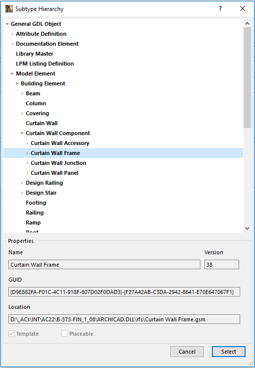
In order to be handled by ARCHICAD as a curtain wall frame component, the library part should be a child of “Curtain Wall Frame” subtype. This subtype provides the necessary fix named optional parameters which handle the data transfer between the library part and ARCHICAD.
In order to provide information of the frame type to ARCHICAD the values of the ac_iCWFrameType and ac_bButtGlazedFrame fix named optional parameters have to be set. These parameters define the Frame Type and Geometry User Interface Dialog. The ac_iCWFrameType parameter can also affect the 2D representation of the frame handled by ARCHICAD, if the Floor Plan and Section / Projection Mode of the frames is set to Symbolic, and the cutting geometric data of the connecting curtain wall frames.
If the simple Frame Type and Geometry User Interface Dialog is needed and the symbolic representation of the frame can always be a simple block (the frame is not a corner frame or profiled frame), then the ac_iCWFrameType parameter should be set to 0. See profiled frame creation at Create Profiled Curtain Wall Frame and corner frame creation at Create Regular Corner Curtain Wall Frame posts.
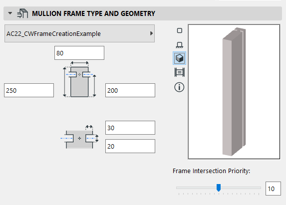
The frame can be created as a butt-glazed frame by setting the ac_bButtGlazedFrame parameter to 1. The Frame Type and Geometry Dialog will show the user interface for butt-glazed frames and the frame depth cannot be set larger than the frame’s back depth.
Coordinate system of a curtain wall frame
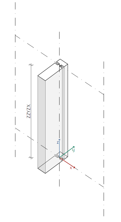
The origo of the coordinate system of the frame and its Z axis is adjusted to the curtain wall grid. The ZZYZX size of the frame refers to the distance between the two grid points of the curtain wall system where the frame subelement is defined.
Cross-sectional frame sizes
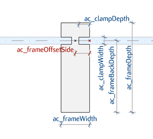
The main curtain wall frame sizes (blue dimension texts on the following picture) can be set and read by ARCHICAD – see Curtain Wall Parameters set and read by ARCHICAD section. These parameters can be modified at the Frame Type and Geometry Dialog and at the library part as well. The frame sizes for listing is calculated by ARCHICAD from them.
The geometry shown on the picture above can be created by the following script in 3D:
! ====================================================================
! Set constant values and variables
! ====================================================================
_halfWidth	= ac_frameWidth / 2
_negDepthSeg	= ac_frameBackDepth
_pozDepthSeg	= ac_frameDepth - ac_frameBackDepth

! ====================================================================
! Set attributes
! ====================================================================
_frameSurf = 1
bSucceed = request{2} ("Building_Material_info", ac_CWFrameBuildMat, "gs_bmat_surface", _frameSurf)

! ====================================================================
! Draw Detailed Frame
! ====================================================================
! Use cprism_{3} to control line elimination
cprism_{3} _frameSurf, _frameSurf, _frameSurf, 1+2,
    12, ZZYZX,
     _halfWidth,		    _pozDepthSeg,	    0,	15,	_frameSurf,
    -_halfWidth,		    _pozDepthSeg,	    0,	15,	_frameSurf,
    -_halfWidth,		    ac_clampWidth / 2,	    0,	15,	_frameSurf,
    -_halfWidth + ac_clampDepth,    ac_clampWidth / 2,	    0,	15,	_frameSurf,
    -_halfWidth + ac_clampDepth,    - ac_clampWidth / 2,    0,	15,	_frameSurf,
    -_halfWidth,		    - ac_clampWidth / 2,    0,	15,	_frameSurf,
    _halfWidth,			    - _negDepthSeg,	    0,	15,	_frameSurf,
    _halfWidth,			    - _negDepthSeg,	    0,	15,	_frameSurf,
    _halfWidth,			    - ac_clampWidth / 2,    0,	15,	_frameSurf,
     _halfWidth - ac_clampDepth,    ac_clampWidth / 2,	    0,	15,	_frameSurf,
    _halfWidth - ac_clampDepth,	    ac_clampWidth / 2,	    0,	15,	_frameSurf,
    _halfWidth,			    ac_clampWidth / 2,	    0,	15,	_frameSurf
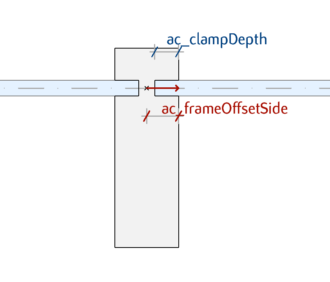
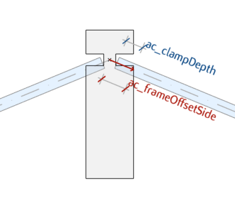
The sizes of the connecting curtain wall panels are affected by the clamp depth and can be affected by the frame width. The fix named optional ac_frameOffsetSide parameter defines the frame width for ARCHICAD: the clamp depth of the panel is measured from this position. The ac_clampDepth and ac_frameOffsetSide parameters are always measured on the centerline of the connecting panels.
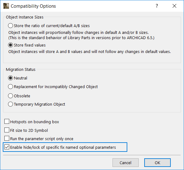
The parameters set and read by ARCHICAD can be hided and locked in GDL script, which has an effect on the Frame Type and Geometry tabpage. To enable this function, the “Enable hide/lock of specific fix named optional parameters” checkbox should be turned on at Compatibility Options:
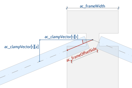
In the following example the ac_frameOffsetSide parameter refers to the section point of the frame side’s boundary and the centerline of the panel. The ac_frameOffsetSide parameter can be calculated from the frame width and the clamp vector, which is provided by ARCHICAD:
The value of this parameter should be set in the parameterscript:
if abs(ac_ClampVector[1][1]) > EPS  then
	_frameAngle = atn(ac_ClampVector[1][2]/ac_ClampVector[1][1])
else
	_frameAngle = 0		! Boundary Frame
endif
ac_frameOffsetSide = (ac_frameWidth / 2) / abs(cos(_frameAngle))
parameters ac_frameOffsetSide = ac_frameOffsetSide
The X component of the first clamp vector is zero when only one panel connects to the frame. This condition can be used to define whether the frame is at the boundary of the curtain wall.
Note that the geometry of the clamp is not optimized for corner situations in this example.
Boundary Frame positioning
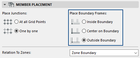
At Curtain Wall System / Member Placement settings the placement of the boundary frames can be set by the User. As previously mentioned, the coordinate system of the curtain wall frame is always adjusted to the grid, therefore the positioning of the frame has to be handled by GDL. The placement type is provided by ARCHICAD through the CW_BOUNDARY_PLACEMENT global variable.
! Modify position in case of Boundary Frames
if CW_BOUNDARY_PLACEMENT <> 0 then
	if CW_BOUNDARY_PLACEMENT = 1 then
		addx - ac_frameWidth / 2
	else
		addx ac_frameWidth / 2
	endif
endif
Symbolic frame representation
At Curtain Wall System / Floor Plan and Section / Projection Mode settings the display mode for cut components can be set by the User. In case of Projected display mode the 2D representation of the frames is projected from the 3D GDL model using its geometry and attributes. If the display mode is set to Symbolic, the 2D representation of the frames is handled by ARCHICAD.
For Symbolic representation ARCHICAD draws a simple block for the frame provided by the ac_frameWidth, ac_frameDepth and ac_frameBackDepth cross-sectional sizes. The attributes of the 2D representation should be given in GDL by the ac_CWFrameBuildMat, ac_CWFrameCutLinePen and ac_CWFrameCutLineType fix named optional parameters.
In order to create a correct attribute representation for switching between symbolic and projected display modes, these fix named optional parameters are recommended to be used in the library parts’ scripts.
! ====================================================================
! Set attributes
! ====================================================================
building_material ac_CWFrameBuildMat

_frameSurf = 1
bSucceed = request{2} ("Building_Material_info", ac_CWFrameBuildMat, "gs_bmat_surface", _frameSurf)

sect_attrs{2} ac_CWFrameCutLinePen, ac_CWFrameCutLineType