The User Documentation explains how Setting Library Part Defaults is made available for library packages. Once you have understood the method, you can jump right into it by continuing with Creating parammapping.xml and MappingDefinitions.json.
Editing parameter defaults rely on a chain of differently formatted data that includes the following:
-
Library part parameter
-
parammapping.xml/MappingDefinitions.json
-
Mapping Value Table
-
Attribute list
All of these communicate with their direct neighbor(s) only.
Library part parameter
This is most likely already familiar to you. Library part parameters can be found in the GDL Editor’s parameter list or the hsf format’s paramlist.xml file. These two are the same – they contain the same data in different file formats.
<Length Name="B">
	<Description><![CDATA["Dimension 2"]]></Description>
	<Fix/>
	<Value>0.52</Value>
</Length>
<PenColor Name="gs_fill_pen">
	<Description><![CDATA["Fill Pen"]]></Description>
	<Fix/>
	<Flags>
		<ParFlg_Child/>
	</Flags>
	<Value>19</Value>
</PenColor>
The following data is stored for each parameter:
-
Type (marked with a “category tag”, such as Length or PenColor)
-
Name (after the Name tag)
-
Description (inside the Description tag)
-
Value (inside the Value tag)
-
and possible additional flags
If you look at the pen color parameter’s value, you can see an integer number corresponding to one of the 255 pen colors available for each pen set. This same logic applies when using the Mapping Value Tables (see below).
The only important data for editable parameter defaults is the Name of the parameter, which will be referenced in the following step.
parammapping.xml/MappingDefinitions.json
parammapping.xml is stored in the hsf format, while MappingDefinitions.json is its equivalent in the binary builds. They essentially store data for the same purpose, with the only difference being that parammapping.xml is per library part, while MappingDefinitions.json is per library package.
parammapping.xml
A parammapping file for a library part containing only the two parameters shown above would look like this:
<?xml version="1.0" encoding="UTF-8"?>
<ParameterMapping>
	<Parameter Name="B" Meaning="Armchair 01/B/Length_0.52" />
	<Parameter Name="gs_fill_pen" Meaning="Armchair 01/gs_fill_pen/Furnishing_FillPen" />
</ParameterMapping>
As you can see, it links each parameter’s Name (see above) to a custom Meaning name. For easier handling, it is recommended to include the library part’s name and the parameter’s name in the Meaning if you have unique identifiers. If you use the same Meaning for multiple objects in a library, a group name may be used instead (e.g., Chairs/gs_fill_pen/Furnishing_FillPen).
MappingDefinitions.json
MappingDefinitions.json is a central collection of all the parammapping.xml files inside a library package. It adds the libPartId value for each block so the parameters can also be identified in the library package’s context.
Its content is generated by the LP_XMLConverter but can be manually edited later on, even without rebuilding the .lcf, as the data in the parammapping.xml file is not included inside the .lcf file. If you want to edit the mapping definitions of an existing library package, you only have to extract the package, edit the MappingDefinitions.json, and then re-pack the .libpack.
[
    {
        "libPartId": "AE852D80-F15A-400E-9CAA-8ABA1E456BE1",
        "parameters": [
            {
                "paramName": "B",
                "meaning": "Armchair 01/B/Length_0.52"
            },
            {
                "paramName": "gs_fill_pen",
                "meaning": "Armchair 01/gs_fill_pen/Furnishing_FillPen"
            }
        ]
    }
]
Overall, the parammapping.xml/MappingDefinitions.json files link a Meaning name (which is used as an identifier later on) to each parameter name (that you wish to have editable default).
Mapping Value Table
All previous files and data can be found inside a single library package. However, Mapping Value Tables (and attribute lists) are stored in Archicad plan files or templates. Handling Mapping Value Tables is described in Setting Library Part Defaults section of the User Documentation.
This is an example Mapping Value Table entry of the two parameters discussed so far:
[
  {
    "meaning": "Armchair 01/B/Length_0.52",
    "type": "Length",
    "value": 0.508
  },
  {
    "meaning": "Armchair 01/gs_fill_pen/Furnishing_FillPen",
    "type": "PenColor",
    "value": 91
  }
]
Here, the Meaning name (given in the previous step) gets assigned a different parameter value with the Value tag. Parameter Type (the same categories are used as in paramlist.xml) also resurfaces here to give additional context for the users. Additionally, Archicad uses this data to differentiate between Meaning names given to multiple parameter types.
Mapping Value Tables take care of the default value modification, as they contain the changed values (e.g., “B” is changed from 0.52 to 0.63, and the pen color is changed from 19 to 91).
When you import a Mapping Value Table into Archicad, it replaces all registered default parameter values based on the Meaning name (which means multiple library parts’ parameters can be changed simultaneously if the same Meaning name is given to them).
Attribute list
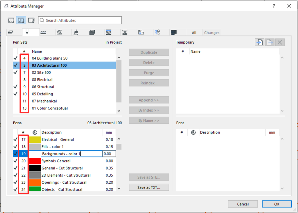
We need to modify default parameter values mainly because of possible differences between attribute lists in Archicad. As you have seen, attribute type parameters store a number reference to the assigned attribute value, also known as the attribute index.
Attribute indices can be looked up in Archicad under Options/Element Attributes/Attribute Manager’s “#” column:

All other types of parameters can be changed as well. For example, if you have a preferred leg style for kitchen furniture, you can set the style selector parameter’s default value to that style.
Also, if you are working in an imperial system-based environment, the length parameters can be adjusted as well. All you have to do is calculate the required imperial length’s metric equivalent and set it in the Mapping Value Table. In the Armchair Length example above, 0.52 meters is closest to 20 inches, equivalent to 0.508 meters. If you set the length value in the Mapping Value Table to 0.508 (as shown in the example above) and set the Working Units to be inch-based, it will show exactly 20 inches.