Attributes in can be created using the surface, fill and line type dialog boxes. These floor plan attributes can be referenced from any GDL script. Attributes can also be defined in GDL scripts. There are two different cases:
- Attribute definition in the MASTER_GDL script.
The MASTER_GDL script is interpreted when the library that contains it is loaded in the memory. The MASTER_GDL attributes are merged into the floor plan attributes; attributes with the same names are not replaced. Once the MASTER_GDL is loaded, the attributes defined in it can be referenced from any script. - Attribute definition in library parts.
The surfaces and textures defined this way can be used in the script and its second generation scripts. Fills and line types defined and used in the master or 2D script have the same behavior as if they were defined in the MASTER_GDL script, but only if used by name or index (not through a parameter). Fills and line types defined in the master or 3D script can’t be accessed in the 3D script.
The Check GDL Script command in the script window helps to verify whether the surface, fill, line type or style parameters are correct.
When a surface, fill, line type or style is different in the 3D interpretation of the library part from the intended one, but there is no error message, this probably means that one or more of the parameter values are incorrect. The Check GDL Scripts command will help you with detailed messages to find these parameters.
DEFINE MATERIAL
DEFINE MATERIAL name type,
        surface_red, surface_green, surface_blue
        [, ambient_ce, diffuse_ce, specular_ce, transparent_ce,
        shining, transparency_attenuation
        [, specular_red, specular_green, specular_blue,
        emission_red, emission_green, emission_blue, emission_att]]
        [, fill_index [, fillcolor_index, texture_index]]
Note
This command can contain additional data definition.
See the section called “Additional Data” for details.
Any GDL script can include surface definitions prior to the first reference to that surface name.
This surface can only be used for 3D elements in its own script and its second generation scripts.
name: name of the surface.type: type of the surface. The actual number (n) of parameters that define the surface is different, depending on the type.The meaning of the parameters and their limits are explained in the examples’ comments.
0: general definition, n=16,1: simple definition, n=9 (extra parameters are constants or calculated from given values),2-7: predefined surface types, n=3.The three values are the RGB components of the surface color. Other parameters are constants or calculated from the color.
2: matte,3: metal,4: plastic5: glass,6: glowing,7: constant,10: general definition with fill parameter, n=17,11: simple definition with fill parameter, n=10,12-17: predefined surface types with fill parameter, n=4,20: general definition with fill, color index of fill and index of texture parameters, n=19,21: simple definition with fill, color index of fill and index of texture parameters, n=12,22-27: predefined surface types with fill, color index of fill and index of texture parameters, n=6.20-27: Special meanings for types 20-27: If the pen number is zero, vectorial hatches will be generated with the active pen.Zero value for a texture or fill index allows you to define surfaces without a vectorial hatch or texture.
Example 1:
Surfaces with solid colors
DEFINE MATERIAL "water" 0,
        0.5284, 0.5989, 0.6167,! surface RGB [0.0..1.0]
        1.0,                   ! ambient coefficient [0.0..1.0]
        0.5,                   ! diffuse coefficient [0.0..1.0]
        0.5,                   ! specular coeff. [0.0..1.0]
        0.9,                   ! transparent coeff. [0.0..1.0]
        2.0,                   ! shining [0.0..100.0]
        1,                     ! transparency atten. [0.0..4.0]
        0.5284, 0.5989, 0.6167,! specular RGB [0.0..1.0]
        0, 0, 0,               ! emission RGB [0.0..1.0]
        0.0                    ! emission atten. [0.0..65.5]
DEFINE MATERIAL "asphalt" 1,
        0.1995, 0.2023, 0.2418,! surface RGB [0.0..1.0]
        1.0, 1.0, 0.0, 0.0,
        !      ambient, diffuse, specular, transparent
        !      coefficients [0.0..1.0]
        0,               ! shining [0..100]
        0                ! transparency attenuation [0..4]
DEFINE MATERIAL "matte red" 2,
        1.0, 0.0, 0.0    ! surface RGB [0.0..1.0]
Example 2:
Surface with fill
DEFINE MATERIAL "Brick-Red" 10,
        0.878294, 0.398199, 0.109468,
        0.58, 0.85, 0.0, 0.0,
        0,
        0.0,
        0.878401, 0.513481, 0.412253,
        0.0, 0.0, 0.0,
        0,
        IND(FILL, "common brick")    ! fill index
Example 3:
Surface with fill and texture
DEFINE MATERIAL "Yellow Brick+*" 20,
        1, 1, 0,         ! surface RGB [0.0 .. 1.0]
        0.58, 0.85, 0, 0,
        !      ambient, diffuse, specular, transparent
        !      coefficients [0.0 .. 1.0]
        0,               ! shining [0.0 .. 100.0]
        0,               ! transparency attenuation [0.0 .. 4.0]
        0.878401, 0.513481, 0.412253, ! specular RGB [0.0 .. 1.0]
        0, 0, 0,         ! emission RGB [0.0 .. 1.0]
        0,               ! emission attenuation [0.0 .. 65.5]
        IND(FILL, "common brick"), 61,
        IND(TEXTURE, "Brick")
        !      Fill index, color index, texture index
DEFINE MATERIAL BASED_ON
DEFINE MATERIAL name [,] BASED_ON orig_name [,] PARAMETERS name1 = expr1 [, ...]
        [[,] ADDITIONAL_DATA name1 = expr1 [, ...]]
Surface definition based on an existing surface.
Specified parameters of the original surface will be overwritten by the new values, other parameters remain untouched.
Using the command without actual parameters results in a surface exactly the same as the original, but with a different name.
Parameter values of a surface can be obtained using the REQUEST{2} (“Material_info”, …) function.
orig_name: name of the original surface (name of an existing, previously defined GDL or floor plan surface).namei: surface parameter name to be overwritten by a new value. Names corresponding to parameters of surface definition:gs_mat_surface_r, gs_mat_surface_g, gs_mat_surface_b: (surface RGB [0.0..1.0])gs_mat_ambient: (ambient coefficient [0.0..1.0])gs_mat_diffuse: (diffuse coefficient [0.0..1.0])gs_mat_specular: (specular coefficient [0.0..1.0])gs_mat_transparent: (transparent coefficient [0.0..1.0])gs_mat_shining: (shininess [0.0..100.0])gs_mat_transp_att: (transparency attenuation [0.0..4.0])gs_mat_specular_r, gs_mat_specular_g, gs_mat_specular_b: (specular color RGB [0.0..1.0])gs_mat_emission_r, gs_mat_emission_g, gs_mat_emission_b: (emission color RGB [0.0..1.0])gs_mat_emission_att: (emission attenuation [0.0..65.5])gs_mat_fill_ind: (fill index)gs_mat_fillcolor_ind: (fill color index)gs_mat_texture_ind: (texture index)expri: new value to overwrite the specified parameter of the surface. Value ranges are the same as at the surface definition.
Example:
n = REQUEST{2} ("Material_info", "Brick-Face", "gs_mat_emission_rgb",
        em_r, em_g, em_b)
em_r = em_r + (1 - em_r) / 3
em_g = em_g + (1 - em_g) / 3
em_b = em_b + (1 - em_b) / 3
DEFINE MATERIAL "Brick-Face light" [,] BASED_ON "Brick-Face"
        PARAMETERS gs_mat_emission_r = em_r,
        gs_mat_emission_g = em_g, gs_mat_emission_b = em_b
SET MATERIAL "Brick-Face"
BRICK a, b, zzyzx
ADDX a
SET MATERIAL "Brick-Face light"
BRICK a, b, zzyzx
DEFINE TEXTURE
DEFINE TEXTURE name expression, x, y, mask, angle
Any GDL script can include texture definition prior to the first reference to that texture name.
The texture can be used only in the script in which it was defined and its subsequent second generation scripts.
name: name of the texture.expression: picture associated with the texture.
A string expression means a file name, a numerical expression an index of a picture stored in the library part.
A 0 index is a special value which refers to the preview picture of the library part.
x: logical width of the texture.y: logical height of the texture.mask: mask = j1 + 2*j2 + 4*j3 + 8*j4 + 16*j5 + 32*j6 + 64*j7 + 128*j8 + 256*j9, where each j can be 0 or 1.Alpha channel controls (j1… j6):
j1: alpha channel changes the transparency of texture,j2: Bump mapping or surface normal perturbation.
Bump mapping uses the alpha channel to determine the amplitude of the surface normal,
j3: alpha channel changes the diffuse color of texture,j4: alpha channel changes the specular color of texture,j5: alpha channel changes the ambient color of texture,j6: alpha channel changes the surface color of texture,Connection controls (j7… j9): (If the value is zero, normal mode is selected.)

j7: the texture will be shifted randomly,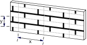
j8: mirroring in x direction,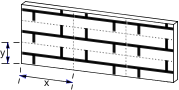
j9: mirroring in y direction.
angle: angle of the rotation.
DEFINE FILL
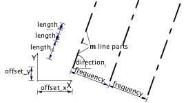
DEFINE FILL name [[,] FILLTYPES_MASK fill_types,]
        pattern1, pattern2, pattern3, pattern4,
        pattern5, pattern6, pattern7, pattern8,
        spacing, angle, n,
        frequency1, direction1, offset_x1, offset_y1, m1,
        length11, ..., length1m,
        ...
        frequencyn, directionn, offset_xn,
        lengthn1, ..., lengthnm
Note
This command can contain additional data definition.
See the section called “Additional Data” for details.
Any GDL script may include fill definitions prior to the first reference to that fill name.
The fill defined this way can be used only for 2D elements in the script in which it was defined and its subsequent second generation-scripts.
name: name of the fill.fill_types: fill_types = j1 + 2*j2 + 4*j3, where each j can be 0 or 1.j1: cut fills,j2: cover fills,j3: drafting fills.If the j bit is set, the defined fill can be used corresponding to its specified type. Default is all fills (0).
pattern definition: pattern1, pattern2, pattern3, pattern4, pattern5, pattern6, pattern7, pattern8: 8 numbers between 0 and 255 representing binary values. Defines the bitmap pattern of the fill.

spacing: hatch spacing – defines a global scaling factor for the whole fill.
All values will be multiplied by this number in both the x and y direction.
angle: global rotation angle in degrees.n: number of hatch lines.frequencyi: frequency of the line (the distance between two lines is spacing * frequencyi).diri: direction angle of the line in degrees.offset_xi, offset_yi: offset of the line from the origin.mi: number of line parts.lengthij: length of the line parts (the real length is spacing * lengthij). Line parts are segments and spaces following each other.
First line part is a segment, zero length means a dot.
The bitmap pattern is only defined by the pattern1… pattern8 parameters and is used when the display options for Polygon Fills are set
to “Bitmap Pattern”. To define it, choose the smallest unit of the fill, and represent it as dots and empty spaces using a rectangular grid with 8×8 locations.
The 8 pattern parameters are decimal representations of the binary values in the lines of the grid (a dot is 1, an empty space is 0).
The vectorial hatch is defined by the second part of the fill definition as a collection of dashed lines repeated with a given frequency (frequencyi).
Each line of the collection is described by its direction (directioni), its offset from the origin (offset_xi, offset_yi)
and the dashed line definition which contains segments and spaces with the given length (lengthij) following each other.
Note
Only simple fills can be defined with the DEFINE FILL command.
There is no possibility to define symbol fills with this command.
Example:
DEFINE FILL "brick" 85, 255, 136, 255,
        34, 255, 136, 255,
        0.08333, 0.0, 4,
        1.0, 0.0, 0.0, 0.0, 0,
        3.0, 90.0, 0.0, 0.0, 2,
        1.0, 1.0,
        3.0, 90.0, 1.5, 1.0, 4,
        1.0, 3.0, 1.0, 1.0,
        1.5, 90.0, 0.75, 3.0, 2,
        1.0, 5.0
Bitmap pattern:
Pattern:         Binary value:
pattern1 = 85    01010101  • • • •
pattern2 = 255   11111111 ••••••••
pattern3 = 136   10001000 •   •
pattern4 = 255   11111111 ••••••••
pattern5 = 34    00100010   •   •
pattern6 = 255   11111111 ••••••••
pattern7 = 136   10001000 •   •
pattern8 = 255   11111111 ••••••••
| View: | Vectorial hatch: |
 |
 |
DEFINE FILLA
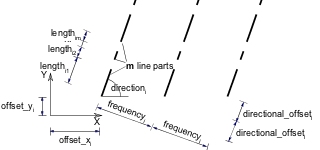
DEFINE FILLA name [,] [FILLTYPES_MASK fill_types,]
        pattern1, pattern2, pattern3, pattern4,
        pattern5, pattern6, pattern7, pattern8,
        spacing_x, spacing_y, angle, n,
        frequency1, directional_offset1, direction1,
        offset_x1, offset_y1, m1,
        length11, ..., length1m,
        ...
        frequencyn, directional_offsetn, directionn,
        offset_xn, offset_yn, mn,
        lengthn1, ..., lengthnm
Note
This command can contain additional data definition.
See the section called “Additional Data” for details.
An extended DEFINE FILL statement.

spacing_x, spacing_y: spacing factor in the x and y direction, respectively.
These two parameters define a global scaling factor for the whole fill.
All values in the x direction will be multiplied by spacing_x and all values in the y direction will be multiplied by spacing_y.
directional_offseti: the offset of the beginning of the next similar hatch line, measured along the line’s direction.
Each line of the series will be drawn at a distance defined by frequencyi with an offset defined by directional_offseti.
The real length of the offset will be modulated by the defined spacing.
Example:
DEFINE FILLA "TEST" 8, 142, 128, 232,
        8, 142, 128, 232,
        0.5, 0.5, 0, 2,
        2, 1, 90, 0,
        0, 2, 1, 1,
        1, 2, 0, 0, 0,
        2, 1, 3
FILL "TEST"
POLY2 4, 6,
        -0.5, -0.5, 12, -0.5,
        12, 6, -0.5, 6
Bitmap pattern:
Pattern:      Binary value:
pat1 = 8      00001000      •
pat2 = 142    10001110  •   •••
pat3 = 128    10000000  •
pat4 = 232    11101000  ••• •
pat5 = 8      00001000      •
pat6 = 142    10001110  •   •••
pat7 = 128    10000000  •
pat8 = 232    11101000  ••• •
| View: | Vectorial hatch: |
 |
 |
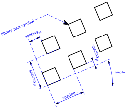
DEFINE SYMBOL_FILL
DEFINE SYMBOL_FILL name [,][FILLTYPES_MASK fill_types,]
        pat1, pat2, pat3, pat4, pat5, pat6, pat7, pat8,
        spacingx1, spacingy1, spacingx2, spacingy2,
        angle, scaling1, scaling2, macro_name [,] PARAMETERS [name1
        = value1, ..., namen = valuen]
Note
This command can contain additional data definition.
See the section called “Additional Data” for details.
An extended DEFINE FILL statement, which allows you to include a library part drawing in a fill definition.
The usage of macro_name and the parameters are the same as for the CALL command.
spacingx1, spacingx2: horizontal spacings.spacingy1, spacingy2: vertical spacings.scaling1: horizontal scale.scaling2: vertical scale.macro_name: the name of the library part.DEFINE SOLID_FILL
DEFINE SOLID_FILL name [[,] FILLTYPES_MASK fill_types]
Defines a solid fill.
Note
This command can contain additional data definition.
See the section called “Additional Data” for details.
DEFINE EMPTY_FILL
DEFINE EMPTY_FILL name [[,] FILLTYPES_MASK fill_types]
Defines an empty fill.
Note
This command can contain additional data definition.
See the section called “Additional Data” for details.
DEFINE LINEAR_GRADIENT_FILL
DEFINE LINEAR_GRADIENT_FILL name [[,] FILLTYPES_MASK fill_types]
Define linear gradient fill.
DEFINE RADIAL_GRADIENT_FILL
DEFINE RADIAL_GRADIENT_FILL name [[,] FILLTYPES_MASK fill_types]
Define radial gradient fill.
DEFINE TRANSLUCENT_FILL
DEFINE TRANSLUCENT_FILL name [[,] FILLTYPES_MASK fill_types]
        pat1, pat2, pat3, pat4, pat5, pat6, pat7, pat8,
        percentage
Define a fill, which shows the background and foreground colors in mixture defined by the given percentage value.
percentage: percentage of foreground color opacity;
0 displays background color only (like empty fill), 100 displays the foreground color only (like solid fill).
DEFINE IMAGE_FILL
DEFINE IMAGE_FILL name image_name [[,] FILLTYPES_MASK fill_types]
        part1, part2, part3, part4, part5, part6, part7, part8,
        image_vert_size, image_hor_size, image_mask, image_rotangle
Define a fill based on an image pattern.
image_name: name of the pattern image loaded in the current library.image_vert_size, image_hor_size: model size of the pattern.image_mask: tiling directiveimage_mask = 1024*j11 + 2048*j12, where each j can be 0 or 1.For more information about laying out images on a surface see the DEFINE TEXTURE command.
j11: mirroring in x directionj12: mirroring in y directionimage_rotangle: rotation angle of the pattern from the normal coordinate system.DEFINE LINE_TYPE
DEFINE LINE_TYPE name spacing, n,
        length1, ..., lengthn
Note
This command can contain additional data definition.
See the section called “Additional Data” for details.
Any GDL script may include line type definitions prior to the first reference to that line-type name.
The line type defined this way can be used only for 2D elements in the script in which it was defined and its subsequent second generation scripts.
name: name of the line type.spacing: spacing factor.n: number of the line parts.lengthi: length of the line parts (the real length is spacing * lengthi). Line parts consist of segments and spaces.
First line part is a segment, zero length means a dot.
Note
Only simple line types – i.e. consisting only of segments and spaces – can be defined
with this command, defining symbol line types can be done with the DEFINE SYMBOL_LINE command.
DEFINE SYMBOL_LINE
DEFINE SYMBOL_LINE name dash, gap, macro_name PARAMETERS [name1 = value1,
        ...
        namen = valuen]
Note
This command can contain additional data definition.
See the section called “Additional Data” for details.
An extended DEFINE LINE statement, which allows you to include a library part drawing in a line definition.
The usage of macro_name and the parameters are the same as for the CALL command.
dash: scale of both line components.gap: gap between each component.DEFINE STYLE
DEFINE STYLE name font_family, size, anchor, face_code
Recommended to be used with the TEXT2 and TEXT commands.
GDL scripts may include style definitions prior to the first reference to that style name.
The style defined this way can be used only in the script in which it was defined and its subsequent second generation scripts.
name: name of the style.font_family: name of the used font family (e.g., Garamond).size: height of the “l” character in millimeters in paper space or meters in model space.If the defined style is used with the TEXT2 and TEXT commands, size means character heights in millimeters.
If used with PARAGRAPH strings in the RICHTEXT2 and RICHTEXT commands,
size meaning millimeters or meters depends on the fixed_height parameter of the TEXTBLOCK definition,
while the outline and shadow face_code values and the anchor values are not effective.
anchor: code of the position point in the text.
face_code: a combination of the following values:face_code = j1 + 2*j2 + 4*j3, where each j can be 0 or 1.j1: bold,j2: italic,j3: underline,If face_code = 0, then style is normal.
DEFINE STYLE{2}
DEFINE STYLE{2} name font_family, size, face_code
New version of style definition, recommended to be used with PARAGRAPH definitions.
name: name of the style.font_family: name of the used font family (e.g., Garamond).size: height of the characters in mm or m in model space.face_code: a combination of the following values:face_code = j1 + 2*j2 + 4*j3 + 32*j6 + 64*j7 + 128*j8, where each j can be 0 or 1.j1: bold,j2: italic,j3: underline,j6: superscript,j7: subscript,j8: strikethrough.If face_code = 0, then style is normal.
If the defined style is used with the TEXT2 command, size means character heights in millimeters,
while the superscript, subscript and strikethrough face_code values are not effective.
If used with PARAGRAPH strings in the RICHTEXT2 and RICHTEXT commands,
size meaning millimeters or meters depends on the fixed_height parameter of the TEXTBLOCK definition.
PARAGRAPH
PARAGRAPH name alignment, firstline_indent,
        left_indent, right_indent, line_spacing [,
        tab_position1, ...]
    [PEN index]
    [[SET] STYLE style1]
    [[SET] MATERIAL index]
    'string1'
    'string2'
    ...
    'string n'
    [PEN index]
    [[SET] STYLE style2]
    [[SET] MATERIAL index]
    'string1'
    'string2'
    ...
    'string n'
    ...
ENDPARAGRAPH
GDL scripts may include paragraph definitions prior to the first reference to that paragraph name.
The paragraph defined this way can be used only in the script in which it was defined and its subsequent second generation scripts.
A paragraph is defined to be a sequence of an arbitrary number of strings (max 256 characters long each) with different attributes:
style, pen and surface (3D).
If no attributes are specified inside the paragraph definition, actual (or default) attributes are used.
The new lines included in a paragraph string (using the special character ‘n’) will automatically split the string
into identical paragraphs, each containing one line.
Paragraph definitions can be referenced by name in the TEXTBLOCK command.
All length type parameters (firstline_indent, left_indent, right_indent, tab_position) meaning millimeters or meters
depends on the fixed_height parameter of the TEXTBLOCK definition.
name: name of the paragraph. Can be either string or integer.
Integer identifiers works only with the TEXTBLOCK_ command
alignment: alignment of the paragraph strings. Possible values:1: left aligned,2: center aligned,3: right aligned,4: full justified.firstline_indent: first line indentation, in mm or m in model space.left_indent: left indentation, in mm or m in model space.right_indent: right indentation, in mm or m in model space.line_spacing: line spacing factor. The default distance between the lines (character size + distance to the next line)
defined by the actual style will be multiplied by this number.
tab_positioni: consecutive tabulator positions (each relative to the beginning of the paragraph), in mm or m in model space.
Tabulators in the paragraph strings will snap to these positions.
If no tabulator positions are specified, default values are used (12.7 mm).
Works only with ‘t’ special character.
stringi: part of the text. Can be either constant string or string type parameter.
TEXTBLOCK
TEXTBLOCK name width, anchor, angle, width_factor, charspace_factor, fixed_height,
        'string_expr1' [, 'string_expr2', ...]
Textblock definition. GDL scripts may include textblock definitions prior to the first reference to that textblock name.
The textblock defined this way can be used only in the script in which it was defined and its subsequent second generation scripts.
A textblock is defined to be a sequence of an arbitrary number of strings or paragraphs which can be placed
using the RICHTEXT2 command and the RICHTEXT command.
Use the REQUEST (“TEXTBLOCK_INFO”, …) function to obtain information on the calculated width and height of a textblock.
name: name of the textblock, string type value.width: textblock width in mm or m in model space, if 0 it is calculated automatically.anchor: code of the position point in the text.angle: rotation angle of the textblock in degrees.width_factor: Character widths defined by the actual style will be multiplied by this number.charspace_factor: The horizontal distance between two characters will be multiplied by this number.fixed_height: Possible values:1: the placed TEXTBLOCK will be scale-independent and all specified length type parameters will mean millimeters,0: the placed TEXTBLOCK will be scale-dependent and all specified length type parameters will mean meters in model space.string_expri: means paragraph name if it was previously defined, simple string otherwise (with default paragraph parameters).TEXTBLOCK_
TEXTBLOCK_ name width, anchor, angle, width_factor, charspace_factor, fixed_height, n,
        'expr_1' [, 'expr_2', ..., 'expr_n']
Similar to the TEXTBLOCK command.
The meaning of all the parameters are the same, with the following additions:
expr_i: paragraph names can be either string or integer types within one textblock.n: number of listed expr_i names
Attribute definitions can contain optional additional data definitions after the ADDITIONAL_DATA keyword.
The additional data must be entered after the previously defined parameters of the attribute command.
An additional data has a name (namei) and a value (valuei), which can be an expression of any type, even an array.
If a string parameter name ends with the substring “_file”, its value is considered to be a file name and will be included in the archive project.
Different meanings of additional data can be defined and used by the executing application.
Additional data definition is available in the following commands:
DEFINE MATERIAL parameters [[,] ADDITIONAL_DATA name1 = value1, name2 = value2, ...]
DEFINE MATERIAL name [,] BASED_ON orig_name [,] PARAMETERS name1 = expr1 [, ...]
        [[,] ADDITIONAL_DATA name1 = expr1 [, ...]]
DEFINE FILL parameters [[,] ADDITIONAL_DATA name1 = value1, name2 = value2, ...]
DEFINE FILLA parameters [[,] ADDITIONAL_DATA name1 = value1, name2 = value2, ...]
DEFINE SYMBOL_FILL parameters
        [[,] ADDITIONAL_DATA name1 = value1, name2 = value2, ...]
DEFINE SOLID_FILL name [[,] FILLTYPES_MASK fill_types]
        [[,] ADDITIONAL_DATA name1 = value1, name2 = value2, ...]
DEFINE EMPTY_FILL name [[,] FILLTYPES_MASK fill_types]
        [[,] ADDITIONAL_DATA name1 = value1, name2 = value2, ...]
DEFINE LINEAR_GRADIENT_FILL name [[,] FILLTYPES_MASK fill_types]
        [[,] ADDITIONAL_DATA name1 = value1, name2 = value2, ...]
DEFINE RADIAL_GRADIENT_FILL name [[,] FILLTYPES_MASK fill_types]
        [[,] ADDITIONAL_DATA name1 = value1, name2 = value2, ...]
DEFINE TRANSLUCENT_FILL name [[,] FILLTYPES_MASK fill_types]
        pat1, pat2, pat3, pat4, pat5, pat6, pat7, pat8,
        percentage [[,] ADDITIONAL_DATA name1 = value1, name2 = value2, ...]
DEFINE IMAGE_FILL name image_name [[,] FILLTYPES_MASK fill_types]
        part1, part2, part3, part4, part5, part6, part7, part8,
        image_vert_size, image_hor_size, image_mask, image_rotangle
        [[,] ADDITIONAL_DATA name1 = value1, name2 = value2, ...]
DEFINE LINE_TYPE parameters [[,] ADDITIONAL_DATA name1 = value1, name2 = value2, ...]
DEFINE SYMBOL_LINE parameters
        [[,] ADDITIONAL_DATA name1 = value1, name2 = value2, ...]